TM Class HC Fitness Product Model No. WEEVSY62000 Serial No. USER'S MANUAL Write the serial number in the space above for reference. Serial Number Decal (Under Seat) QUESTIONS? As a manufacturer, we are committed to providing complete customer satisfaction. If you have questions, or if there are missing or damaged parts, we will guarantee complete satisfaction through our Customer Service Department. Please CALL: 0345-089009 Or WRITE: ICON Health & Fitness Ltd.
TABLE OF CONTENTS IMPORTANT PRECAUTIONS . . . . . . . . . . . . . . . . . . . . . . . . . . . . . . . . . . . . . . . . . . . . . . . . . . . . . . . . . . . . .3 BEFORE YOU BEGIN . . . . . . . . . . . . . . . . . . . . . . . . . . . . . . . . . . . . . . . . . . . . . . . . . . . . . . . . . . . . . . . . . . .4 ASSEMBLY . . . . . . . . . . . . . . . . . . . . . . . . . . . . . . . . . . . . . . . . . . . . . . . . . . . . . . . . . . . . . . . . . . . . . . . . . . .5 HOW TO USE THE HOME GYM SYSTEM . . .
IMPORTANT PRECAUTIONS WARNING: To reduce the risk of serious injury, read the following important precautions before using the home gym system. 1. It is the responsibility of the owner to ensure that all users of the home gym system are adequately informed of all precautions. arms before kneeling on the assist arm. The assist arm can drop quickly when your body weight is placed on it. 2. Read all instructions in this manual before using the home gym system. 12.
BEFORE YOU BEGIN questions, please call our Customer Service Department. To help us assist you, please note the product model number and serial number before calling. The model number is WEEVSY62000. The serial number can be found on a decal attached to the home gym system (see the front cover of this manual). Thank you for selecting the versatile WEIDER® PRO 9645 home gym system. The PRO 9645 offers a selection of weight stations designed to develop every major muscle group of the body.
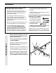
ASSEMBLY Before beginning assembly, carefully read the following information and instructions: • As you assemble the home gym system be sure that all parts are oriented as shown in the drawings. • Place all parts of the home gym system in a cleared area and remove the packing materials; do not dispose of the packing materials until assembly is completed. • Tighten all parts as you assemble them, unless instructed to do otherwise.
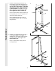
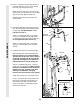
2. Slide the Assist Upright (74) and the Leg Press Upright (56) onto the indicated 5/16” x 2 1/2” Carriage Bolts (1) in the Stabiliser (5). The high side of the brackets on the Assist Upright and Leg Press Upright should be on the side shown. Hand tighten four 5/16” Nylon Locknuts (3) onto the Carriage Bolts. Do not tighten the Nylon Locknuts yet. 2 27 87 High Sides of Brackets 91 74 Press a 2” Square Inner Cap (27) into the Leg Press Upright (56).
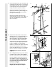
4. Press a 2” Square Inner Cap (27) into the end of the Top Frame (55). Press a 1 3/4” Square Inner Cap (44) into each end of the crossbar on the Top Frame. Press two Round Inner Caps (111) into the top of the crossbar. 4 11 55 111 44 8 27 3 Attach the Top Frame (55) to the Assist Upright (74) and the Leg Press Upright (56) with two 5/16” x 2 3/4” Bolts (11) and two 5/16” Nylon Locknuts (3).
7. Press a Weight Tube Bumper (64) into the end of the Short Weight Tube (108). Insert the Weight Tube into the front stack of Weights (25). Be sure that the pin on the Weight Tube is sitting in the pin grooves in the top Weight. 7 Holes 62 Lubricate the inside of the holes in a Top Weight (65). Set the Top Weight onto the front stack of Weights (25). Insert both Long Weight Guides (62) into the stack of Weights. Be sure that the holes in the Weight Guides are at the top, as shown.
. Attach the upper ends of the Short Weight Guides (73) to the Top Frame (55) with a 5/16” x 6” Bolt (60), two 1/2” x 3/4” Spacers (61), and a 5/16” Nylon Locknut (3). 61 3 61 3 60 73 55 60 FRAME ASSEMBLY Attach the upper ends of the Long Weight Guides (62) to the Top Frame (55) in the same manner. 9 62 10. Locate and open the parts bag labelled “ARM ASSEMBLY.” 10 ARM ASSEMBLY Press one 2” Square Inner Cap (27) into the end of the Leg Press Arm (96).
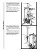
12. Press a 1” Round Inner Cap (49) into one of the Press Arms (46). Press a 1 3/4” Square Inner Cap (44) into the Press Arm. 12 44 49 Attach the Press Arm (46) to one side of the Press Frame (17) with two 5/16” x 2 1/2” Bolts (22) and two 5/16” Nylon Locknuts (3). 46 Assemble the other Press Arm (46) in the same manner. 22 46 3 17 13. Identify the Right Arm (48) and the Left Arm (47). Note the position of the welded bracket on each Arm. Arm identification is very important for step 14.
15. See the inset drawing. Attach the Military Press Arm (84) to the Pivot Arm (101) with two 5/16” x 2 1/4” Bolts (33) and two 5/16” Nylon Locknuts (3). 15 32 49 32 Press two 1 1/2” Square Inner Caps (32) into the Military Press Arm (84). Press two 1” Round Inner Caps (49) into the Military Press Arm. Slide two 5” Plastic Handgrips (83) onto the Military Press Arm. Attach the Pivot Arm (101) to the Assist Upright (74) with a 3/8” x 3 1/4” Bolt (67) and a 3/8” Nylon Locknut (21).
17. Attach the Left Pull-up Arm (75) and the Right Pull-up Arm (77) to the Assist Upright (74) with two 5/16” x 2 3/4” Bolts (11) and two 5/16” Nylon Locknuts (3). 17 ARM ASSEMBLY Attach the Left Dip Arm (78) and the Right Dip Arm (79) to the Assist Upright (74) with two 5/16” x 2 3/4” Bolts (11) and two 5/16” Nylon Locknuts (3). 3 11 77 109 109 Wet the end of the Left Pull-up Arm (75) with soapy water. Slide a Short Handgrip (113) onto the Left Pull-up Arm. Repeat with the Right Pull-up Arm (77).
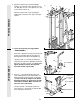
20. Wrap the High Cable (58) around a “V”-Pulley (50). Attach the “V”-Pulley and a Long Cable Trap (31) to the indicated bracket on the Front Upright (42) with a 3/8” x 2 1/2” Bolt (86) and a 3/8” Nylon Locknut (21). Be sure that the Long Cable Trap is positioned to hold the Cable in place. 20 86 31 58 50 Bracket 21 42 21. Route the High Cable (58) around the “V”Pulley (50) on the Left Arm (47).
24. See the inset drawing. Wrap the High Cable (58) around a 3 1/2” Pulley (15). Attach the Pulley and a set of Pulley Covers (114) to the upper hole in a Long “U”-Bracket (57) with a 3/8” x 2” Bolt (12) and a 3/8” Nylon Locknut (21). Note: This may be pre-assembled. Be sure that the small tabs on the Pulley Covers are in the position shown and that the Cable and Pulley move smoothly. 24 Small tabs should be up. 58 114 114 15 21 57 58 114 12 57 CABLE ASSEMBLY 25.
27. Locate the Low Cable (23). Route the Low Cable under the 3 1/2” Low Pulley (102). Be sure that the end of the Cable with the ball is on the indicated side of the Press Frame (17) and that the Cable is between the Pulley and the crossbar on the Press Frame. Tighten the 3/8” Nylon Locknut (21) and the 3/8” x 3 3/4” Bolt (not shown). 27 21 102 23 Ball 17 Crossbar 28. Wrap the Low Cable (23) around the 3 1/2” Pulley (15).
31. Attach the end of the Low Cable (23) to the Long “U”-Bracket (57) with a 1/4” Nylon Locknut (2) and a 1/4” Flat Washer (10). Do not completely tighten the Nylon Locknut. It should be threaded onto the end of the Cable so only a couple of threads are showing above the Nylon Locknut, as shown in the inset drawing. 31 57 2 2 10 23 10 57 23 CABLE ASSEMBLY 32. Attach the High Cable (58) to a Small “U”Bracket (71) with a 1/4” Nylon Locknut (2) and a 1/4” Flat Washer (10).
34. Wrap the Military Press Cable (72) around a “V”-Pulley (50). Attach the “V”-Pulley to the Top Frame (55) with a 3/8” x 2 1/2” Bolt (86) and a 3/8” Nylon Locknut (21). 34 55 50 Wrap the Military Press Cable (72) around a 3 1/2” Pulley (15). Attach the Pulley, a set of Pulley Covers (114), and a 3/8” Flat Washer (9) to the indicated bracket on the Assist Arm (105) with a 3/8” x 2” Bolt (12) and a 3/8” Nylon Locknut (21).
36. Slide a 5/16” Flat Washer (8) onto a 5/16” x 2 3/4” Bolt (11). Insert the Bolt through the indicated hole in the Pivot Arm (101). The Bolt must be inserted from the side shown. Slide another 5/16” Flat Washer (8) onto the Bolt. Fully tighten a 5/16” Nylon Jam Nut (93) onto the Bolt. 36 112 93 9 Wrap the Military Press Cable (72) around a 3 1/2” Pulley (15).
38. Locate the Leg Press Cable (99). Attach the end of the Leg Press Cable to the Long “U”Bracket (57) with a 1/4” Nylon Locknut (2) and a 1/4” Flat Washer (10). Do not completely tighten the Nylon Locknut. It should be threaded onto the end of the Cable only a couple of turns, as shown in the inset drawing. 38 2 57 10 Wrap the Leg Press Cable (99) around a 3 1/2” Pulley (15).
40. Locate and open the parts bag labelled “SEAT ASSEMBLY.” 40 Insert a 1/4” x 2 1/2” Carriage Bolt (92) through the centre hole in a Seat Plate (37). Attach the Seat Plate to the Rear Backrest (85) with two 1/4” x 3/4” Screws (18). 85 56 Insert the 1/4” x 2 1/2” Carriage Bolt (92) through the indicated hole in the Leg Press Upright (56). Tighten a 1/4” Nylon Locknut (2) with a 1/4” Flat Washer (10) onto the Carriage Bolt.
43. Attach the Front Backrest (41) to the Front Upright (42) with two 1/4” x 2 1/2” Screws (43) and two 1/4” Flat Washers (10). The Backrest must be oriented as shown. 43 42 41 43 10 Thick End 44. Press a 1 1/2” Square Inner Cap (32) into the Front Seat Frame (36). 44 13 Insert a 1/4” x 2” Carriage Bolt (38) through the centre hole in the Seat Plate (37). Attach the Seat Plate to the Seat (13) with two 1/4” x 3/4” Screws (18).
47. Press two 3/4” Round Inner Caps (34) into each Pad Tube (28). 47 36 SEAT ASSEMBLY Insert a Pad Tube (28) into the Front Seat Frame (36). Slide a Foam Pad (30) onto each end of the Pad Tube. 30 34 28 Insert the other Pad Tube (28) into the Leg Lever (29). Slide a Foam Foam Pad (30) onto each end of the Pad Tube. 34 30 29 48. Align the welded tubes on the Leg Press Plate (95) with one set of holes in the Leg Press Arm (96). Attach the Leg Press Plate to the Leg Press Arm with the Press Pin (97).
HOW TO USE THE HOME GYM SYSTEM The instructions below describe how each part of the home gym system can be adjusted. IMPORTANT: When attaching the lat bar or nylon strap, make sure that the attachments are in the correct starting position for the exercise to be performed. If there is any slack in the cables or chain as an exercise is performed, the effectiveness of the exercise will be reduced. CHANGING THE WEIGHT SETTING The home gym system features two weight stacks.
ATTACHING AND REMOVING THE SEAT 40 36 To attach the Seat (13), set the bracket on the Front Seat Frame (36) onto the indicated pins on the Front Upright (42). Attach the Front Seat Frame to the Front Upright with the 5/16” x 2 3/4” Carriage Bolt (14) and the Seat Knob (40). 13 42 14 Pin For some exercises, the Seat (13) must be removed. First, be sure that the chain is not attached to the leg lever.
WEIGHT RESISTANCE CHART This chart shows the approximate weight resistance at each weight station. “Top” refers to the 6,5-pound top weight. The other numbers refer to the 12,5-pound weight plates. The butterfly arm resistance listed is the resistance for each butterfly arm. Note: The actual resistance at each weight station may vary due to differences in individual weight plates, as well as friction between the cables, pulleys, and weight guides.
TROUBLE-SHOOTING AND MAINTENANCE Inspect and tighten all parts each time you use the home gym system. Replace any worn parts immediately. The home gym system can be cleaned using a damp cloth and mild non-abrasive detergent. Do not use solvents. TIGHTENING THE CABLES Woven cable, the type of cable used on the home gym system, can stretch slightly when it is first used. If there is slack in the cables before resistance is felt, the cables should be tightened.
CABLE DIAGRAMS The cable diagrams on this page show the proper routing of the High Cable (58), the Low Cable (23), the Military Press Cable (72), and the Leg Press Cable (99). Use the diagrams to be sure that the four cables and the cable traps have been assembled correctly. If the cables have not been correctly routed, the home gym system will not function properly and damage may occur. The insets show the proper positioning of the cable traps.
ORDERING REPLACEMENT PARTS If you encounter any difficulties with this product, or if you need to order replacement parts, call the ICON Health & Fitness Ltd. office, or write: ICON Health & Fitness Ltd. Unit 4 Revie Road Industrial Estate Revie Road Leeds LS11 8JG Tel: Country Code: 0345-089009 Fax: 0113-2411120 To help us assist you, please be prepared to give the following information: 1. The MODEL NUMBER of the product (WEEVSY62000) 2. The NAME of the product (WEIDER® PRO 9645 home gym system) 3.
REMOVE THIS PART IDENTIFICATION CHART FROM THE MANUAL This chart is provided to help you identify the small parts used in assembly. Important: Some parts may have been pre-assembled for shipping purposes. If you cannot find a part in the parts bags, check to see if it has been pre-assembled. The number in parenthesis below each part refers to the key number of the part. The second number refers to the quantity needed for assembly.
2" Square Inner Cap (27) 2" Square Outer Cap (51) 1 1/2" Square Inner Cap (32) 1 3/4" Square Inner Cap (44) 1" x 2" Inner Cap (107) 1" Round Inner Cap (49) Round Inner Cap (111) 1 1/4" Round Inner Cap (109) 3/4" Round Inner Cap (34) 1" Round Cover Cap (70) 1" Square Inner Cap (6) 5/16" x 2" Eyebolt (35) 1/2" x 3/4" Spacer (61) 5/8" x 9/16" Spacer (7)
5/16" x 1 3/4" Bolt (24) 3/8" x 1 3/4" Bolt (76) 3/8" Flat Washer (9) 5/16" Flat Washer (8) 1/4" Flat Washer (10) 3/8" Nylon Jam Nut (112) 3/8" Nylon Locknut (21) 5/16" Nylon Jam Nut (93) 5/16" Nylon Locknut (3) 5/16" x 2 3/4" Carriage Bolt (14) 5/16" x 2 3/4" Bolt (11) 3/8" x 2 1/2" Bolt (86) 5/16" x 2 1/2" Carriage Bolt (1) 1/4" x 2 1/2" Screw (43) 5/16" x 2 1/4" Bolt (33) 3/8" x 2" Bolt (12) 5/16" x 2 1/2" Bolt (22) 1/4" x 2 1/2" Carriage Bolt (92) 1" Retainer (69) 1/4" x 1/2" Screw (1
81 REMOVE THIS PART LIST/EXPLODED DRAWING CHART FROM THE MANUAL
PART LIST—Model No. WEEVSY62000 Key Qty. No.
109 109 103 113 80 78 109 75 10 2 21 114 88 103 11 11 57 9 77 99 15 83 54 3 27 12 114 3 3 11 51 52 5 11 26 79 8 51 3 1 114 112 9 65 10 2 3 74 15 113 109 11 60 53 19 61 43 91 87 3 25 64 39 116 10 10 83 3 1 115 3 88 9 2 15 8 24 27 11 8 63 114 71 72 73 3 104 110 21 1 112 82 9 92 9 12 76 9 101 8 13 114 21 3 33 43 10 21 105 114 15 9 11 88 106 84 49 32 114 21 94 9 96 15 66 12 21 20 114 8 83 93 87 9