
User's Manual

6
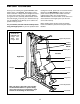
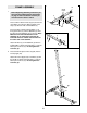
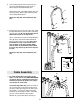
1.
Press a 40mm x 60mm Inner Cap (27) into the end
of the Base (4). Press two 40mm x 60mm Outer
Caps (73) onto the ends of the Stabiliser (5).
Insert four M10 x 55mm Carriage Bolts (1) up
through the Base (4) and the Stabiliser (5). Rest
the Base and the Stabiliser flat on the floor. Note:
Make sure that the indented holes in the
Stabilizer are on the bottom. Note that the
indicated holes are smaller than the holes on
the other side of the Stabilizer.
Attach the Base (4) to the Stabiliser (5) with the
indicated M10 x 55mm Carriage Bolts (1) and two
M10 Nylon Locknuts (21). Do not tighten the
Locknuts yet.
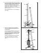
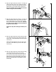
2. Press the 25mm Square Inner Cap (86) into the
Front Upright (42).
Attach the Front Upright (42) to the Base (4) with
the two M10 x 55mm Carriage Bolts (1) and two
M10 Nylon Locknuts (21). Do not tighten the
Locknuts yet.
Before beginning assembly, make sure you
have read and understood the information
on page 5. This introduction will save you
more time than it takes to read it.
FRAME ASSEMBLY
1
2
73
1
Small
Holes
Indents
21
5
1
4
4
73
27
86
42
21
21
4
1