Model No.WEEVSY49220 Serial No. USER'S MANUAL (Write the serial number in the space above for reference.) Serial Number Decal (under seat) QUESTIONS? As a manufacturer, we are committed to providing complete customer satisfaction. If you have questions, or if there are missing parts, please call: 08457 089 009 Or write: ICON Health & Fitness, Ltd. Unit 4 Revie Road Industrial Estate Revie Road Beeston Leeds, LS118JG UK email: csuk@iconeurope.
TABLE OF CONTENTS IMPORTANT PRECAUTIONS . . . . . . . . . . . . . . . . . . . . . . . . . . . . . . . . . . . . . . . . . . . . . . . . . . . . . . . . . . . . . 3 BEFORE YOU BEGIN . . . . . . . . . . . . . . . . . . . . . . . . . . . . . . . . . . . . . . . . . . . . . . . . . . . . . . . . . . . . . . . . . . . 4 ASSEMBLY . . . . . . . . . . . . . . . . . . . . . . . . . . . . . . . . . . . . . . . . . . . . . . . . . . . . . . . . . . . . . . . . . . . . . . . . . . . 5 ADJUSTMENTS . . . . . . . . . . .
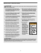
IMPORTANT PRECAUTIONS WARNING: To reduce the risk of serious injury, read the following important precautions before using the weight system. 1. Read all instructions in this manual and in the accompanying literature before using the weight system. Use the weight system only as described in this manual. 11. Make sure that the cables remain on the pulleys at all times. If the cables bind whilst you are exercising, stop immediately and make sure that the cables are on all of the pulleys. 2.
BEFORE YOU BEGIN reading this manual, please call our Customer Service Department at 0845 089 009. To help us assist you, please note the product model number and serial number before calling. The model number is WEEVSY49220. The serial number can be found on a decal attached to the weight system (see the front cover of this manual). Thank you for selecting the versatile WEIDER® 9150 weight system.
ASSEMBLY Make sure you have the following tools: Make Assembly Easier for Yourself • Two adjustable spanners Everything in this manual is designed to ensure that the weight system can be assembled successfully by anyone. Before beginning assembly, make sure to read the information on this page. This brief introduction will save you much more time than it takes to read it.
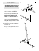
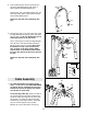
1 FRAME ASSEMBLY 1. 73 Small Holes Before beginning assembly, make sure you have read and understood the information on page 5. This introduction will save you more time than it takes to read it. 5 21 73 Press a 40mm x 60mm Inner Cap (27) into the end of the Base (4). Press two 40mm x 60mm Outer Caps (73) onto the ends of the Stabiliser (5). Indents 1 4 Insert four M10 x 55mm Carriage Bolts (1) up through the Base (4) and the Stabiliser (5). Rest the Base and the Stabiliser flat on the floor.
3. Insert the two Weight Guides (62) into the indicated holes in the Base (4) and the Stabiliser (5). Be sure that the Weight Guides are oriented with the holes in the positions shown. Attach the Weight Guides to the Base and the Stabiliser with two M10 x 78mm Bolts (14), two 17.5mm Spacers (77), two M10 Washers (9), and two M10 Nylon Locknuts (21). 3 Hole 62 Slide two Weight Bumpers (19) onto the Weight Guides (62). Hole Hole 9 19 21 19 9 77 14 5 4.
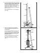
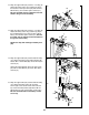
5. Press four 40mm x 60mm Inner Caps (27) into the ends of the Top Frame (55). 5 27 55 27 27 27 6. Hold the Top Frame (55) on top of the Front Upright (42) between the Weight Guides (62). Attach the Top Frame to the Front Upright with two M10 x 60mm Bolts (7), the Support Plate (71), and two M10 Nylon Locknuts (21). 6 7 61 55 60 Attach the Weight Guides (62) to the Top Frame (55) with the M10 x 155mm Bolt (60), two 15mm Spacers (61), two M10 Washers (9), and an M10 Nylon Locknut (21).
. Press a 50mm Square Inner Cap (44) into the end of the Right Butterfly Arm (48). Press a Sleeve (89) into the Right Butterfly Arm. 9 89 47 Wet the lower end of the Right Butterfly Arm (48) with soapy water. Slide a Large Foam Pad (45) onto the Right Butterfly Arm. 48 Repeat this step with the Left Butterfly Arm (47). 45 44 45 44 10. Lubricate the axles on the Top Frame (55). Orient the Right Butterfly Arm (48) as shown and slide it onto the right axle.
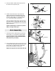
12. Wrap the High Cable (23) around a “V”-Pulley (6). Attach the Pulley and a Long Cable Trap (50) to the bracket on the Top Frame (55) with an M10 x 60mm Bolt (7) and an M10 Nylon Locknut (21). Be sure the Cable Trap is oriented to hold the Cable in the groove of the Pulley. 12 50 7 6 55 23 21 13. Wrap the High Cable (23) around a “V”-Pulley (6). Attach the Pulley and a Long Cable Trap (50) to the Left Butterfly Arm (47) with an M10 x 60mm Bolt (7) and an M10 Nylon Locknut (21).
16. Route the High Cable (23) up through the Top Frame (55), around the 115mm Pulley (74), and back down through the Top Frame. Attach the Pulley inside the Top Frame with an M10 x 75mm Bolt (76), two 17.5mm Spacers (77), two M10 Washers (9), and an M10 Nylon Locknut (21). 16 74 76 77 55 9 77 9 21 23 17. Attach the High Cable (23) to the “U”-bracket (57) with an M8 Washer (70) and an M8 Nylon Locknut (3).
20. Wrap the Low Cable (69) around a 90mm Pulley (15). Attach the Pulley and a pair of Pulley Covers (40) to the second set of holes from the bottom of the two Pulley Plates (58) with an M10 x 52mm Bolt (12) and an M10 Nylon Locknut (21). Be sure the small tabs on the Pulley Covers are on bottom. 20 58 15 12 40 21 40 Small Tab 21. Wrap the Low Cable (69) around a 90mm Pulley (15).
24. Wrap the Low Cable (69) around a 90mm Pulley (15). Attach the Pulley and a pair of Pulley Covers (40) to the Press Frame (17) with the M10 x 135mm Bolt (75) used in step 22, and an M10 Nylon Locknut (21). Be sure the large tabs on the Pulley Covers are on the side shown. 24 40 69 15 21 40 Large Tab 75 17 25. Wrap the Low Cable (69) around a 90mm Pulley (15).
27. Attach the Backrest (41) to the Front Upright (42) with two M6 x 73mm Bolts (43) and two M6 Washers (78). 27 43 78 42 43 78 41 28. Press a 38mm Square Inner Cap (32) into the end of the Seat Frame (36). Attach the Bumper (67) to the Seat Frame (36) with the M5 x 20mm Self-tapping Screw (80). 28 13 Insert the M6 x 50mm Carriage Bolt (38) into the centre hole in the Seat Plate (37). Attach the wide end of the Seat (13) to the Seat Plate with two M6 x 16mm Screws (18).
31. Attach the Seat Frame (36) to the Front Upright (42) with the M10 x 80mm Carriage Bolt (11) and the Seat Knob (49). 31 49 36 11 42 32. Attach the Curl Pad (24) to the Curl Post (35) with two M6 x 16mm Screws (18). 32 35 24 18 33. Make sure that all parts have been properly tightened. The use of the remaining parts will be explained in ADJUSTMENTS, beginning on the following page. Before using the weight system, pull each cable a few times to be sure that the cables move smoothly over the pulleys.
ADJUSTMENTS This section explains how to adjust the weight system. See the EXERCISE GUIDELINES on page 21 for important information about how to get the most benefit from your exercise program. Also, refer to the accompanying exercise guide to see the correct form for several exercises. Make sure all parts are properly tightened each time the weight system is used. Replace any worn parts immediately. The weight system can be cleaned with a damp cloth and a mild, non-abrasive detergent. Do not use solvents.
ATTACHING THE SEAT FRAME To attach the Seat Frame (36) to the Front Upright (42), slide one of the three slots in the bracket on the Seat Frame onto the pin on the Front Upright. Note: The Seat Frame can be adjusted to three heights using the different slots in the bracket. Secure the Seat Frame to the Upright with the M10 x 80mm Carriage Bolt (11) and the Seat Knob (49). 49 Slot 11 For some exercises, the Seat Frame (36) must be removed. First, be sure that the chain is not attached to the leg lever.
WEIGHT RESISTANCE CHART The chart below shows the approximate weight resistance at each exercise station. “Top” refers to the 6-lb. top weight. The other numbers refer to the 12.5 lb. weight plates. Weight resistance shown for the butterfly arm station is for each butterfly arm. Note: The actual resistance at each station may vary due to differences in individual weight plates as well as friction between the cables, pulleys, and weight guides. Weight High Pulley (lbs.) Butterfly Arm (lbs.
TROUBLESHOOTING AND MAINTENANCE Make sure all parts are properly tightened each time the weight system is used. Replace any worn parts immediately. The weight system can be cleaned using a damp cloth and mild non-abrasive detergent. Do not use solvents. TIGHTENING THE CABLES Woven cable, the type of cable used on the weight system, can stretch slightly when it is first used. If there is slack in the cables before resistance is felt, the cables should be tightened.
CABLE DIAGRAMS The cable diagrams below show the proper routing of the High Cable (23) and the Low Cable (69). Use the diagrams to make sure that the cables and the cable traps have been assembled correctly. If the cables have not been correctly routed, the weight system will not function properly and damage may occur. The numbers show the correct route for each cable. Make sure that the cable traps do not touch or bind the cables.
EXERCISE GUIDELINES THE FOUR BASIC TYPES OF WORKOUTS PERSONALISING YOUR EXERCISE PROGRAM Muscle Building To increase the size and strength of your muscles, push them close to their maximum capacity. Your muscles will continually adapt and grow as you progressively increase the intensity of your exercise. You can adjust the intensity level of an individual exercise in two ways: • by changing the amount of weight used • by changing the number of repetitions or sets performed.
Rest for a short period of time after each set. The ideal resting periods are: • Rest for three minutes after each set for a muscle building workout. • Rest for one minute after each set for a toning workout. • Rest for 30 seconds after each set for a weight loss workout. Plan to spend the first couple of weeks familiarising yourself with the equipment and learning the proper form for each exercise. slowly as you stretch and do not bounce.
EXERCISE MONDAY WEIGHT SETS REPS WEIGHT SETS REPS WEIGHT SETS REPS Date: / / AEROBIC EXERCISE TUESDAY Date: / / WEDNESDAY EXERCISE Date: / / THURSDAY AEROBIC EXERCISE Date: / / EXERCISE FRIDAY Date: / / Make photocopies of this page for scheduling and recording your workouts.
ORDERING REPLACEMENT PARTS To order replacement parts, contact the ICON Health & Fitness, Ltd. office, or write: ICON Health & Fitness, Ltd.
This chart is provided to help you identify the small parts used in assembly. The number in parenthesis below each part refers to the key number of the part from the PART LIST in the centre of this manual. Important: Some parts may have been pre-assembled for shipping purposes. If you cannot find a part in the parts bags, check to see if it has been pre-assembled. Note: Assembly is divided into four stages: 1) frame assembly, 2) arm assembly, 3) cable assembly, and 4) seat assembly.
40mm x 60mm Inner Cap (27) 50mm Square Inner Cap (44) 38mm Square Inner Cap (32) 40mm x 60mm Outer Cap (73) 25mm Round Inner Cap (10) 19mm Round Inner Cap (34) Cable Clip (53) 25mm Square Inner Cap (86) 25mm Round Cover Cap (62) 25mm Retainer (68)
M6 Washer (78) M8 Washer (70) M10 Washer (9) M6 Nylon Locknut (2) M8 Nylon Locknut (3) M10 Nylon Locknut (21) M6 x 16mm Screw (18) M5 x 20mm Self-tapping Screw (80) M6 x 73mm Bolt (43) M10 x 70mm Bolt (22) M10 x 55mm Carriage Bolt (1) M10 x 60mm Bolt (7) M6 x 50mm Carriage Bolt (38) M10 x 52mm Bolt (12) M6 x 50mm Bolt (33) M10 x 45mm Bolt (88) M8 x 45mm Bolt (66) M10 Thick Spacer (81) 12.5mm Spacer (82) 15mm Spacer (61) 17.
REMOVE THIS PART LIST/EXPLODED DRAWING FROM THE MANUAL.
PART LIST—Model No. WEEVSY49220 Key No. Qty.
21 25 62 9 61 19 72 63 56 57 66 23 3 19 3 70 84 62 61 26 83 9 60 18 18 59 78 78 52 78 18 78 15 18 27 9 21 58 21 9 21 20 77 21 74 39 40 15 40 21 21 77 88 71 21 9 40 50 10 12 58 12 53 40 7 55 82 9 76 27 15 7 6 82 73 9 27 76 21 27 9 7 1 77 50 6 44 45 21 5 73 48 89 65 68 21 14 21 47 4 44 45 7 14 21 1 40 21 31 6 50 21 40 79 86 49 21 9 15 21 9 21 42 35 53 51 18 21 40 81 21 15 11 43 78 43 78 54