
User's Manual

12
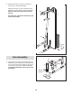
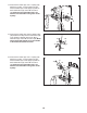
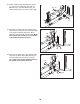
8. Attach the Shroud (17) to the Top Frame (4)
with two M4 x 19mm Screws (69).
A
ttach the Shroud (17) to the brackets on the
Stabilizer (2) with two M4 x 19mm Screws (69).
M
ake sure that the brackets are inside the
Shroud.
See steps 2–6. Tighten the Locknuts (56, 58)
used in these steps.
8
69
6
9
1
7
4
69
69
Bracket
2
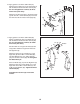
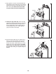
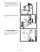
9. Apply grease to the M10 x 70mm Bolt Set (73).
Orient the Leg Lever (8) so that the welded sup-
port is on the side shown. Attach the Leg Lever
to the Front Leg (7) with the Bolt Set. Do not
overtighten the Bolt Set; the Leg Lever must
pivot freely.
9
73
73
Grease
Welded
Support
7
8
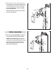
Arm Assembly