Model No. WEEVSY3426.1 Serial No. Write the serial number in the space above for reference. USERʼS MANUAL Serial Number Decal (under seat) QUESTIONS? If you have questions, or if there are missing parts, please contact us: UK Call: 08457 089 009 From Ireland: 053 92 36102 Website: www.iconsupport.eu E-mail: csuk@iconeurope.com Write: ICON Health & Fitness, Ltd. c/o HI Group PLC Express Way Whitwood, West Yorkshire WF10 5QJ UK AUSTRALIA Call: 1-800-237-173 E-mail: australiacc@iconfitness.
TABLE OF CONTENTS WARNING DECAL PLACEMENT . . . . . . . . . . . . . . . . . . . . . . . . . . . . . . . . . . . . . . . . . . . . . . . . . . . . . . . . . . . . . .2 IMPORTANT PRECAUTIONS . . . . . . . . . . . . . . . . . . . . . . . . . . . . . . . . . . . . . . . . . . . . . . . . . . . . . . . . . . . . . . . .3 BEFORE YOU BEGIN . . . . . . . . . . . . . . . . . . . . . . . . . . . . . . . . . . . . . . . . . . . . . . . . . . . . . . . . . . . . . . . . . . . . . .5 PART IDENTIFICATION CHART . . . . .
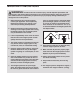
IMPORTANT PRECAUTIONS WARNING: To reduce the risk of serious injury, read all important precautions and instructions in this manual and all warnings on your weight system before using your weight system. ICON assumes no responsibility for personal injury or property damage sustained by or through the use of this product. view. To prevent access to the weight stack, place the weight system in a corner or bay of a room, as shown in the drawing below. There must be no more than 3 ft. 4 in.
16. Never release the arms, leg lever, lat bar, or ankle strap while weights are raised. The weights will fall with great force. 13. Always secure the weight stack with the lock pin and lock after exercising to prevent unauthorized use of the weight system (see LOCKING THE WEIGHT STACK on page 24). 17. Always disconnect the lat bar from the weight system when performing an exercise that does not require the lat bar. 14. Make sure that the cables remain on the pulleys at all times.
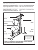
BEFORE YOU BEGIN model number and serial number before contacting us. The model number and the location of the serial number decal are shown on the front cover of this manual. Thank you for selecting the versatile WEIDER® PRO 4500 weight system. The 4500 weight system offers a selection of weight stations designed to develop every major muscle group of the body. For your benefit, read this manual carefully before using your weight system.
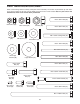
PART IDENTIFICATION CHART Refer to the drawings below to identify small parts used in assembly. The number in parentheses by each drawing is the key number of the part, from the PART LIST near the end of this manual. Note: If a part is not in the hardware kit, check to see if it has been preattached.
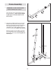
ASSEMBLY To make assembly easier, carefully read the following information and instructions: • The following tools (not included) may be required for assembly: • Assembly requires two persons. two adjustable wrenches • Because of its weight and size, the weight system should be assembled in the location where it will be used. Make sure that there is enough clearance to walk around the weight system while you assemble it.
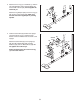
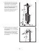
1. Frame Assembly 1 IMPORTANT: To make assembly easier, read the assembly tips on page 7. 1 Insert four M8 x 75mm Carriage Bolts (78) up through the Base (1). Note: It may be helpful to place tape over the bolt heads to hold them in place. 78 78 2. Orient the two Weight Guides (21) so that the indicated holes are closer to the lower ends. Attach the two Weight Guides and the Base (1) to the Stabilizer (2) with two M10 x 80mm 10.9G Bolts (79), two M10 Washers (57), and two M10 Locknuts (56).
3. Attach the Front Leg (7) to the Base (1) with the two indicated M8 x 75mm Carriage Bolts (78) and two M8 Locknuts (58). Do not tighten the Locknuts yet. 3 Up Attach the Leg Bumper (60) to the Front Leg (7) with an M4 x 19mm Screw (69). Make sure that the end of the Leg Bumper is pointing upward. 69 7 60 58 58 1 78 4. Hold the Seat Frame (6) between the Upright (3) and the Front Leg (7). Orient the Seat Frame so that the welded rods are closer to the Upright.
5. Slide the two Weight Bumpers (27) onto the Weight Guides (21). Orient fourteen Weights (22) so the pin holes are on the bottom, and slide the Weights onto the Weight Guides. 5 21 Insert the Weight Tube (24) into the fourteen Weights (22). Make sure that the pin on the Weight Tube is oriented as shown. Grease 22 Pin Using the included grease packet, lubricate the indicated holes in a Weight (22). Slide the Weight onto the Weight Guides (21). 24 Pin Hole 22 27 6.
7. Attach the Left Cap (19) and the Right Cap (20) to the bottom of the Shroud (17) with two M4 x 10mm Screws (84). 7 18 84 Attach the Top Cap (18) to the top of the Shroud (17) with two M4 x 10mm Screws (84).
8. Attach the Shroud (17) to the Top Frame (4) with two M4 x 19mm Screws (69). Attach the Shroud (17) to the brackets on the Stabilizer (2) with two M4 x 19mm Screws (69). Make sure that the brackets are inside the Shroud. 8 4 69 17 69 See steps 2–6. Tighten the Locknuts (56, 58) used in these steps. 69 Bracket 69 Arm Assembly 9 9. Apply grease to the M10 x 70mm Bolt Set (73). Orient the Leg Lever (8) so that the welded support is on the side shown.
10. Apply grease to an M10 x 90mm Bolt (67). Attach the Pivot Frame (5) to the Top Frame (4) with the Button Bolt and an M10 Locknut (56). Do not overtighten the Locknut; the Pivot Frame must pivot freely. 10 4 56 Attach the two Arm Pins (40) to the Pivot Frame (5) with two M4 x 19mm Screws (69). Insert the Arm Pins into the two holes in the Upright (3). 67 5 69 Holes Grease 40 69 3 40 11. Apply grease to an M10 x 55mm Bolt (66).
12. Apply grease to an M10 x 90mm Bolt (67) and two Arm Bushings (44). Attach the Right Arm (9) to the Pivot Frame (5) with the Button Bolt, the two Arm Bushings, and an M10 Locknut (56). Do not overtighten the Locknut; the Right Arm must pivot freely. 12 Attach the Left Arm (10) to the Pivot Frame (5) in the same manner. 9 Grease 44 67 5 56 10 Grease Cable Assembly 13 13. Refer to the CABLE DIAGRAMS on page 26 as you identify and assemble the cables. Identify the Arm Cable (54).
14. Route the Arm Cable (54) over a V-pulley (46). Attach the V-pulley, a Large Cable Trap (50), and two Guards (41) to the Upright (3) with an M10 x 65mm Bolt (75) and an M10 Locknut (56). Make sure that the Cable Trap is oriented to hold the Cable in the groove of the V-pulley. 15. Route the Arm Cable (54) under a 90mm Pulley (48). Attach the Pulley and two Half Guards (43) to the Double U-bracket (63) with an M10 x 45mm Bolt (81) and an M10 Locknut (56).
17. Apply grease to an M8 x 19mm Shoulder Bolt (65). Attach the Arm Cable (54) to the indicated Cable Pivot (39) with the Shoulder Bolt and an M8 Locknut (58). Make sure that the Cable can pivot freely around the Shoulder Bolt. 17 Grease 65 18. Identify the High Cable (55). Route the High Cable up through the Top Frame (4) and over a 90mm Pulley (48). Attach the Pulley inside of the Top Frame with an M10 x 80mm Bolt (71), two M10 Washers (57), two 19mm Spacers (33), and an M10 Locknut (56). 19.
20. Wrap the High Cable (55) under a 90mm Pulley (48). Attach the Pulley and two Half Guards (43) at the upper hole in the Adjustable U-bracket (45) with an M10 x 45mm Bolt (81) and an M10 Locknut (56). Make sure that the Half Guards are on the outside of the Adjustable Ubracket. 20 55 56 43 48 43 81 45 21. Route the High Cable (55) up through the Top Frame (4) and over a 90mm Thin Pulley (47).
23. Thread an M12 Nut (86) all the way onto the High Cable (55). Place a Large Washer (87) on top of the Weight Tube (24). 23 55 86 Tighten the High Cable (55) into the Weight Tube (24) until all the slack is removed from the cables. Tighten the M12 Nut (86) against the Large Washer (87). 24. Identify the Low Cable (53). Route the Low Cable through the Leg Lever (8) and the Front Leg (7).
26. Attach a 90mm Pulley (48) inside the Upright (3), over the Low Cable (53), with an M10 x 80mm Bolt (71), two M10 Washers (57), two 19mm Spacers (33), and an M10 Locknut (56). 26 56 57 53 27. Route the Low Cable (53) over a 90mm Pulley (48). Attach the Pulley and two Half Guards (43) to the Double U-bracket (63) with an M10 x 45mm Bolt (81) and an M10 Locknut (56). Make sure that the Half Guards are on the outside of the Double U-bracket as shown. 27 43 56 33 3 48 33 63 48 53 43 28.
29. Route the Low Cable (53) over a 90mm Pulley (48). Attach the Pulley, a Cable Trap (51), and two Half Guards (43) to the Adjustable Ubracket (45) at the second hole from the bottom with an M10 x 55mm Bolt (66) and an M10 Locknut (56). 29 56 45 43 66 43 30. Attach the Low Cable (53) to the M10 x 55mm Bolt (66) used in step 28 with an M10 Locknut (56). 51 48 53 30 56 53 66 Seat Assembly 31 31. Attach the Backrest (16) to the Upright (3) with two M6 x 80mm Screws (70) and two M6 Washers (82).
32. Attach the Seat (15) to the Seat Frame (6) with two M6 x 80mm Screws (70) and two M6 Washers (82). 32 15 6 82 70 33. Insert the Pad Tube (29) into the Front Leg (7). Slide two Small Foam Pads (28) onto the Pad Tube. Then, press two Pad Caps (34) onto the Pad Tube. 33 Slide two Small Foam Pads (28) onto the Leg Lever (8). Press two Pad Caps (34) onto the Leg Lever.
34. Orient the Curl Pad (14) so that the holes in the back are closer to the lower edge. Attach the Curl Pad to the Curl Post (13) with two M6 x 16mm Screws (62). 34 14 13 62 35. Make sure that all parts have been properly tightened. The use of the remaining parts will be explained in ADJUSTMENT, beginning on page 23. Before using the weight system, pull each cable a few times to make sure that the cables move smoothly around the pulleys.
ADJUSTMENT This section explains how to adjust the weight system. See the EXERCISE GUIDELINES on page 28 for important information about how to get the most benefit from your exercise program. Also, refer to the accompanying exercise guide to see the correct form for each exercise. Make sure that all parts are properly tightened each time the weight system is used. Replace any worn parts immediately. The weight system can be cleaned with a damp cloth and a mild, non-abrasive detergent.
ARM CONVERSION To use the Arms (9, 10) as butterfly arms, insert the Arm Pins (40) into the holes in the Upright (3) and the Pivot Frame (5) as shown. To use the Arms (9, 10) as press arms, insert the Arm Pins (40) into the holes in the Pivot Frame (5) and the Arms. 3 40 9 Holes USING THE CURL PAD 5 10 14 To use the Curl Pad (14), remove the 64mm Round Inner Cap (30) from the Front Leg (7). Insert the Curl Post (13) into the Front Leg and secure it in place with the Curl Knob (61).
WEIGHT RESISTANCE CHART The chart below shows the approximate weight resistance at each exercise station. Weight resistance shown for the butterfly arm station is for each arm. Note: The actual resistance at each station may vary due to differences in individual weight plates as well as friction between the cables, pulleys, and weight guides. WEIGHT 1 HIGH PULLEY (lbs.) BUTTERFLY ARM (lbs.) PRESS ARM (lbs.) LOW PULLEY (lbs.) LEG LEVER (lbs.
CABLE DIAGRAMS The cable diagrams below show the proper routing of the Low Cable (53), the Arm Cable (54), and the High Cable (55). Use the diagrams to make sure that the cables, cable traps, and guards have been assembled correctly. If the cables have not been correctly routed, the weight system will not function properly and damage may occur. The numbers show the correct route for each cable. Make sure that the cable traps do not touch or bind the cables. 4 High Cable (55) Length: 292 cm (115 in.
MAINTENANCE Make sure that all parts are properly tightened each time you use the weight system. Replace any worn parts immediately. The weight system can be cleaned with a damp cloth and a mild, non-abrasive detergent. Do not use solvents. TIGHTENING THE CABLES Woven cable, the type of cable used on the weight system, can stretch slightly when it is first used. If there is slack in the cables before resistance is felt, the cables should be tightened.
EXERCISE GUIDELINES FOUR TYPES OF STRENGTH WORKOUTS workout, and the numbers of repetitions and sets to complete. Progress at your own pace and be sensitive to your bodyʼs signals. Follow each workout with at least one day of rest. Note: A “repetition” is one complete cycle of an exercise, such as one sit-up. A “set” is a series of repetitions. Warming Up—Start with 5 to 10 minutes of stretching and light exercise.
PART LIST Key No. Qty. 1 2 3 4 5 6 7 8 9 10 11 12 13 14 15 16 17 18 19 20 21 22 23 24 25 26 27 28 29 30 31 32 33 34 35 36 37 38 39 40 41 42 43 44 45 46 47 1 1 1 1 1 1 1 1 1 1 2 1 1 1 1 1 1 1 1 1 2 15 1 1 1 1 2 4 1 4 2 1 10 4 1 2 3 1 2 2 4 2 10 4 1 2 2 Description Key No. Qty.
EXPLODED DRAWING A Model No. WEEVSY3426.
EXPLODED DRAWING B 48 43 81 56 63 56 56 43 75 50 59 41 41 32 43 81 48 66 41 48 70 82 33 58 33 58 59 57 57 4 33 48 55 33 47 71 86 30 33 57 57 55 22 71 76 56 87 57 57 74 24 23 70 58 71 57 48 33 33 17 41 75 57 57 33 84 18 50 46 56 82 56 30 69 58 3 81 48 43 84 59 46 58 56 57 51 56 56 45 68 16 56 48 43 43 43 Model No. WEEVSY3426.
ORDERING REPLACEMENT PARTS To order replacement parts, please see the front cover of this manual. To help us assist you, be prepared to provide the following information when contacting us: • the model number and serial number of the product (see the front cover of this manual) • the name of the product (see the front cover of this manual) • the key number and description of the replacement part(s) (see the PART LIST and the EXPLODED DRAWING near the end of this manual) Part No.