Model No. WEEVSY2996.0 Serial No. Write the serial number in the space above for future reference. Serial Number Decal (under seat) QUESTIONS? As a manufacturer, we are committed to providing complete customer satisfaction. If you have questions, or if there are missing or damaged parts, please call: 08457 089 009 Or write: ICON Health & Fitness, Ltd. Unit 4 Revie Road Industrial Estate Revie Road, Beeston Leeds, LS11 8JG UK email: csuk@iconeurope.
TABLE OF CONTENTS WARNING DECAL PLACEMENT . . . . . . . . . . . . . . . . . . . . . . . . . . . . . . . . . . . . . . . . . . . . . . . . . . . . . . . . . . . . . .2 IMPORTANT PRECAUTIONS . . . . . . . . . . . . . . . . . . . . . . . . . . . . . . . . . . . . . . . . . . . . . . . . . . . . . . . . . . . . . . . . 3 BEFORE YOU BEGIN . . . . . . . . . . . . . . . . . . . . . . . . . . . . . . . . . . . . . . . . . . . . . . . . . . . . . . . . . . . . . . . . . . . . . . 4 PART IDENTIFICATION CHART . . . .
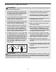
IMPORTANT PRECAUTIONS WARNING: To reduce the risk of serious injury, read the following important precautions before using the weight system. 1. Read all instructions in this manual and all warnings on the weight system before using the weight system. Use the weight system only as described in this manual. 6. Inspect and properly tighten all parts regularly. Replace any worn parts immediately. 7. The weight system is designed to support a maximum user weight of 135 kg (295 lbs). 2.
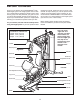
BEFORE YOU BEGIN Thank you for selecting the versatile WEIDER™ PRO 5500 weight system. The weight system offers a selection of weight stations designed to develop every major muscle group of the body. Whether your goal is to tone your body, build dramatic muscle size and strength, or improve your cardiovascular system, the weight system will help you to achieve the specific results you want. reading this manual, please see the front cover of this manual.
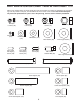
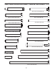
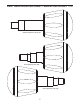
PART IDENTIFICATION CHART—Model No. WEEVSY2996.0 R0706A Refer to the drawings below to identify small parts used in assembly. The number in parentheses by each drawing is the key number of the part, from the PART LIST in the center of this manual. Note: Some small parts may have been preattached. If a part is not in the parts bag, check to see if it has been preattached.
PART IDENTIFICATION CHART—Model No. WEEVSY2996.
PART IDENTIFICATION CHART—Model No. WEEVSY2996.
ASSEMBLY Make sure you have the following tools: Make Assembly Easier • Two adjustable wrenches Everything in this manual is designed to ensure that the weight system can be assembled successfully by anyone. Before beginning assembly, make sure to read the information on this page. This brief introduction will save you much more time than it takes to read it.
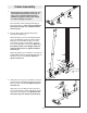
1. Frame Assembly 1 Before beginning assembly, make sure you understand the information in the box on page 8. See the PART IDENTIFICATION CHARTS on pages 5 and 6 of this manual for help identifying small parts. 1 Insert four M8 x 75mm Carriage Bolts (83) up through the Base (1). Note: It may be helpful to place a piece of tape over each Bolt head to hold it in place. 83 2 2. Insert an M8 x 75mm Carriage Bolt (83) up through the Stabilizer (3).
4. Attach the Frame (9) to the Upright (2) with two M8 x 80mm Bolts (100), two M8 Washers (103), and two M8 Nylon Locknuts (78). Do not tighten the Nylon Locknuts yet. 4 9 78 Attach the Frame (9) to the Front Leg (10) with two M8 x 65mm Bolts (101), two M8 Washers (103), and two M8 Nylon Locknuts (78). Do not tighten the Nylon Locknuts yet. 78 78 103 2 78 100 103 103 100 10 101 5.
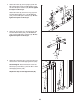
7. Attach a Shroud Cover (23) to the Left and Right Shrouds (21, 22) with two M6 x 28mm Bolts (94), four M6 Washers (114), and two M6 Nylon Locknuts (107). 7 Attach the Shroud Cover (23) to the Top Frame (4) with four M4 x 16mm Self-tapping Screws (110) and four M4 Washers (104). See the inset drawing and attach the other Shroud Cover (23) in the same manner. 114 94 114 4 23 107 104 22 114 114 94 110 110 104 21 8. Note: Some parts have been removed to show this step clearly.
Arm Assembly 9 9. Attach the Butterfly Frame Brace (6) to the Upright (2) with two M8 x 80mm Bolts (100), two M8 Washers (103), and two M8 Nylon Locknuts (78). Do not tighten the Nylon Locknuts yet. 78 100 6 10. Apply grease in the locations shown. Insert a 56.5mm Spacer (69) the indicated hole in the Leg Lever (12). Attach the Leg Lever to the Front Leg (10) with an M10 x 61mm Bolt Set (116). Make sure the indicated rod is oriented as shown. 100 2 10 Grease See the left inset drawing.
12. Apply grease to the locations shown and attach the Left Butterfly Bracket (28) to the Butterfly Frame (5) with an M10 x 80mm Bolt (84) and an M10 Nylon Locknut (77). 12 84 Repeat this step for the Right Butterfly Bracket (29). Tighten the Nylon Locknuts (77, 78, 107) used in steps 2–12. 29 13. Attach a Butterfly Handle (27) to the Left Butterfly Arm (25) with an M10 x 65mm Button Bolt (106), two M10 Washers (80), two 13mm Steel Spacers (109), and an M10 Nylon Locknut (77).
15. Orient a Press Arm Handle (17) with the 90° bend at the top as shown in the inset drawing. Attach a Press Arm Handle (17) to the Right Press Arm (16) with two M10 x 65mm Button Bolts (106), four M10 Washers (80), four 11mm Spacers (99), and two M10 Nylon Locknuts (77). 15 99 80 Repeat this step for the Left Press Arm (not shown). 106 80 99 80 90° Bend 16. Attach the Left Press Arm (15) to the Right Press Arm (16) with an M10 x 110mm Bolt (93), an 90mm Spacer (59) and an M10 nylon Locknut (77).
Cable Assembly 18 18. See the CABLE DIAGRAMS on page 28 to identify the cables as you assemble them. 90 Identify the Butterfly Cable (50). Grease an M8 x 22mm Shoulder Bolt (90). Attach the Cable to the Left Butterfly Bracket (28) with the Shoulder Bolt and an M8 Nylon Locknut (78). Make sure the flat edge of the Cable is against the Butterfly Bracket. Do not overtighten the Shoulder Bolt; the Cable must pivot freely. 19. Wrap the Butterfly Cable (50) over a “V”-pulley (47).
21. Wrap the Butterfly Cable (50) over a “V”-pulley (47). Attach the “V”-pulley, a Long Cable Trap (57), an M10 Washer (80), and two Guards (54) to the Upright (2) with an M10 x 60mm Bolt (79) and an M10 Nylon Locknut (77). 21 54 79 47 22. Grease an M8 x 22mm Shoulder Bolt (90). Attach the Butterfly Cable (50) to the Right Butterfly Arm (29) with the Shoulder Bolt and an M8 Nylon Locknut (78). Make sure the flat edge of the Cable is against the Butterfly Bracket.
24. Route the Lat Cable (49) over a Thin Pulley (24) and down through the Top Frame (4). Hold the Thin Pulley inside the Top Frame. Insert an M10 x 80mm Bolt (84) through an M10 Washer (80), a 19mm Spacer (67), the Top Frame, and the Thin Pulley. 24 49 25. Wrap the Lat Cable (49) under a 90mm Pulley (48). Attach the Pulley, a Cable Trap (56), and two Half Guards (55) at the second hole from the top of the two Pulley Plates (60) with an M10 x 50mm Bolt (97) and an M10 Nylon Locknut (77).
27. Wrap the Lat Cable (49) over a 90mm Pulley (48) and route the Cable down through the Top Frame (4). Attach the Pulley to the Top Frame with an M10 x 80mm Bolt (84), two M10 Washers (80), two 19mm Spacers (67), and an M10 Nylon Locknut (77). 27 84 4 28. Set an M12 Large Washer (98) on top of the Weight Tube (20). Thread the M12 Nut (112) all the way onto the Lat Cable (49). 49 80 67 48 67 28 49 Thread the Lat Cable (49) into the Weight Tube (20) two turns.
30. Attach a 90mm Pulley (48) inside the Front Leg (10) with an M10 x 65mm Bolt (85), two M10 Washers (80), two 13mm Steel Spacers (109), and an M10 Nylon Locknut (77). Make sure the Leg Lever Cable (51) is under the Pulley. 30 85 80 109 10 48 31. Route the Leg Lever Cable (51) under the 89.5mm Spacer (59), through the Upright (2), and under the indicated rod in the Base (1). Wrap the Leg Lever Cable under a 90mm Pulley (48).
33. Wrap the Leg Lever Cable (51) under a 90mm Pulley (48). Attach the Pulley to the Base (1) with an M10 x 45mm Bolt (86), two Half Guards (55), and an M10 Nylon Locknut (77). 33 51 48 86 55 1 34. Wrap the Leg Lever Cable (51) over a 90mm Pulley (48). Attach the Pulley to the Double “U”bracket (61) with an M10 x 45mm Bolt (86), two Half Guards (55), and an M10 Nylon Locknut (77). 55 77 34 77 55 61 48 51 55 35. Wrap the Leg Lever Cable (51) under a 90mm Pulley (48).
36. Wrap the Leg Lever Cable (51) under a 90mm Pulley (48). Attach the Pulley to the Right Press Arm (16) with an M10 x 50mm Bolt (97), two Half Guards (55), a Cable Trap (56), an M10 Washer (80), and an M10 Nylon Locknut (77). Make sure the Cable Trap and Half Guards are oriented as shown. 36 77 37. Wrap the Leg Lever Cable (51) around a “V”-pulley (47).
39. Attach the Leg Lever Cable (51) to the Upright (2) with the M10 x 120mm Bolt (115), an M10 Washer (80), a 7mm Spacer (111), and an M10 Nylon Locknut (77). 39 2 115 51 Seat Assembly 40 114 Repeat this step for the Left Butterfly Pad (34). 35 91 41 Insert the Backrest Frame (7) into the Upright (2) and tighten the Backrest Adjustment Knob (53) into the Upright. Make sure the Adjustment Knob passes through one of the holes in the Backrest Frame. 31 34 88 7 2 114 22 77 26 40.
42. Attach the Seat (32) to the Seat Frame (8) with two M6 x 16mm Screws (88), an M6 x 32mm Screw (89), and an M6 Washer (114). 42 32 Insert the Seat Frame (8) into the Frame (9). Tighten the Seat Adjustment Knob (52) into the Frame and the Seat Frame. Make sure the Adjustment Knob passes through one of the holes in the Seat Frame. 8 89 88 43. Insert a Pad Tube (13) into the indicated hole in the Front Leg (10). Slide a Foam Pad (36) onto each end of the Pad Tube.
45. Attach the Curl Pad (33) to the Curl Post (11) with two M6 x 16mm Screws (88). 45 33 11 88 46. Make sure that all parts have been properly tightened. The use of the remaining parts will be explained in ADJUSTMENTS, beginning on the following page. Before using the weight system, pull each cable a few times to make sure that the cables move smoothly over the pulleys. If one of the cables does not move smoothly, find and correct the problem.
ADJUSTMENTS This section explains how to adjust the weight system. Refer to the accompanying exercise guide to see the correct form for each exercise. Make sure that all parts are properly tightened each time you use the weight system. Replace any worn parts immediately. The weight system can be cleaned with a damp cloth and a mild, non-abrasive detergent. Do not use solvents.
USING THE CURL PAD To use the Curl Pad (33), remove the indicated 50mm Round Inner Cap (39) and insert the Curl Post (11) into the Front Leg (10). Tighten the Curl Adjustment Knob (58) into the Front Leg. Make sure the Adjustment Knob passes through a hole in the Curl Post. 33 When you are performing exercises that do not require the Curl Pad, remove the Curl Pad (33) and reinsert the 50mm Round Inner Cap (39) into the Front Leg (10). Note: You must remove the Curl Pad to use the press arms.
LOCKING THE LEG LEVER To lock or unlock the Leg Lever, remove the Lock Plate Pin (95) from the Lock Plate (14). Move the Lock Plate to either the position shown on the Front Leg (10), or the indicated hole in the Leg Lever (12). Insert the Lock Pin back through the Lock Plate. 10 14 12 Hole 95 WEIGHT RESISTANCE CHART The chart below shows the approximate weight resistance at each exercise station. Note: Weight resistance shown for the butterfly arm station is for each arm.
CABLE DIAGRAM The cable diagram shows the proper routing of the cables (49, 50, 51). Use the diagram to make sure that the cable and the cable traps have been assembled correctly. If the cable has not been correctly routed, the weight system will not function properly and damage may occur. The numbers show the correct route for the cable. Make sure that the cable traps do not touch or bind the cable.
MAINTENANCE Make sure all parts are properly tightened each time you use the weight system. Replace any worn parts immediately. The weight system can be cleaned with a damp cloth and a mild, non-abrasive detergent. Do not use solvents. TIGHTENING THE CABLES Woven cable, the type of cable used on the weight system, can stretch slightly when it is first used. If there is slack in the cables before resistance is felt, the cables should be tightened.
EXERCISE GUIDELINES THE FOUR BASIC TYPES OF WORKOUTS Muscle Building To increase the size and strength of your muscles, push them close to their maximum capacity. Your muscles will continually adapt and grow as you progressively increase the intensity of your exercise. You can adjust the intensity level of an individual exercise in two ways: • by changing the amount of weight used • by changing the number of repetitions or sets performed.
Rest for a short period of time after each set. The ideal resting periods follow: • Rest for three minutes after each set for a muscle building workout. • Rest for one minute after each set for a toning workout. • Rest for 30 seconds after each set for a weight loss workout. Plan to spend the first couple of weeks familiarizing yourself with the equipment and learning the proper form for each exercise. slowly as you stretch and do not bounce.
MONDAY Date: / TUESDAY Date: / / / / / WEDNESDAY Date: THURSDAY Date: / / / / FRIDAY Date: EXERCISE WEIGHT SETS REPS WEIGHT SETS REPS WEIGHT SETS REPS AEROBIC EXERCISE EXERCISE AEROBIC EXERCISE EXERCISE Make photocopies of this page for scheduling and recording your workouts.
PART LIST—Model No. WEEVSY2996.0 Key No. 1 2 3 4 5 6 Qty.
EXPLODED DRAWING—Model No. WEEVSY2996.
EXPLODED DRAWING—Model No. WEEVSY2996.
ORDERING REPLACEMENT PARTS To order replacement parts, contact the ICON Health & Fitness, Ltd. office, or write: ICON Health & Fitness, Ltd. Customer Service Department Unit 4, Revie Road Industrial Estate Revie Road Beeston Leeds, LS118JG UK Tel: 08457 089 009 Outside the UK: 0 (444) 113 387 7133 Fax: 0 (444) 113 387 7125 To help us assist you, please be prepared to give the following information: • the MODEL NUMBER of the product (WEEVSY2996.