
User's Manual

5
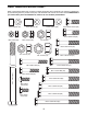
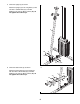
Refer to the drawings below and on page 6 to identify small parts used in assembly. The number in parentheses
b
y each drawing is the key number of the part, from the PART LIST near the end of this manual. IMPORTANT: If
you cannot find a part in the hardware kit, check to see if it has been preassembled.
PART IDENTIFICATION CHART
M10 x 52mm Bolt (67)
M10 x 50mm Bolt (58)
M10 x 32mm Bolt (59)
M10 x 25mm Screw (60)
M8 x 63mm Bolt (61)
M8 x 42mm Bolt (62)
M10 x 75mm Bolt (94)
1/2" x 7" Bolt (64)
M8 Locknut (69)
M10 Locknut (68)
1/2" Nut (84)
5/8" Locknut (75)
1/2" Locknut (70)
M8 x 16mm
Screw (63)
M8 x 20mm
Screw (65)
M10 x 65mm Bolt (37)
M10 x 85mm Bolt (95)
M10 x 95mm Bolt (66)
M10 x 103mm Bolt (57)
27mm Spacer (96)12mm Spacer (91) 22mm Spacer (97)
M10 x 93mm Bolt (99)