
User's Manual

18
3
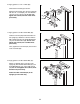
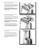
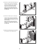
0. Hold a Pulley (42) on the Ab Cable (93) in the
indicated location.
Attach the Pulley (42) and two Cable Guides
(
52) to the Double U-bracket (24) with an M10 x
50mm Bolt (58), two M10 Washers (73), and an
M
10 Locknut (68).
Make sure that the Cable Guides (52) are
holding the Ab Cable (93) in the groove of
the Pulley (42).
68
73
24
42
93
52
5
2
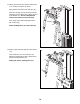
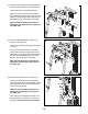
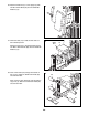
31. See the CABLE DIAGRAM on page 27 and
identify the Low Cable (54).
Route the Low Cable (54) through the Leg
Lever (3), through the Leg (21), and through the
Upright (5) as shown.
Next, route the Low Cable (54) under a Pulley
(42).
Attach the Pulley (42) and two Pulley Covers
(36) inside the Leg Lever (3) with an M10 x
65mm Bolt (37), two M10 Washers (73), two
12mm Spacers (91), and an M10 Locknut (68).
Make sure that the Pulley Covers (36) are
holding the Low Cable (54) in the groove of
the Pulley (42).
31
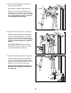
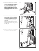
32. Route the Low Cable (54) under a Pulley (42).
Attach the Pulley (42) and two Pulley Covers
(36) inside the Leg (21) with an M10 x 95mm
Bolt (66), two M10 Washers (73), two 27mm
Spacers (96), and an M10 Locknut (68).
Make sure that the Pulley Covers (36) are
holding the Low Cable (54) in the groove of
the Pulley (42).
32
54
3
21
5
37
36
73
91
91
73
68
21
66
73
54
96
96
73
68
36
36
42
42
36
58
7
3
30