
User's Manual

13
1
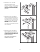
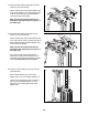
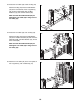
5. See the CABLE DIAGRAM on page 27 and
identify the Arm Cable (51).
Apply grease to an M10 x 32mm Bolt (59).
Attach one end of the Arm Cable (51) to the
R
ight Arm (13) with the M10 x 32mm Bolt (59),
an M10 Washer (73), and an M10 Locknut (68).
Do not overtighten the Locknut; the end of
the Arm Cable must pivot easily.
15
73
68
5
9
13
51
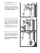
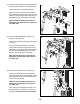
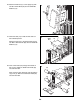
17. Route the Arm Cable (51) under a Pulley (42).
Attach the Pulley (42) and two Cable Guides
(52) to one end of the Offset Double U-bracket
(85) with an M10 x 50mm Bolt (58), two M10
Washers (73), and an M10 Locknut (68).
Make sure that the Cable Guides (52) are
holding the Arm Cable (51) in the groove of
the Pulley (42).
17
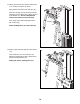
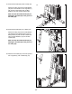
16. Route the Arm Cable (51) over a Pulley (42).
Attach the Pulley (42) and two Cable Guides
(52) to the right U-bracket (22) on the Upright
(5) with an M10 x 50mm Bolt (58), two M10
Washers (73), and an M10 Locknut (68). Make
sure that the Cable Guides are oriented as
shown.
See the inset drawing. Make sure that the
Cable Guides (52) are holding the Arm Cable
(51) in the groove of the Pulley (42).
16
42
42
51
52
52
58
85
73
52
51
73
58
5
52
22
52
52
51
42
Grease
68
73
68