
User's Manual
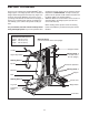
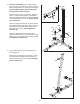
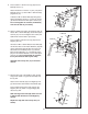

2. See the inset drawing. Press a 50mm Square
Inner Cap (31) into the Base (1). Insert two M10 x
6
5mm Carriage Bolts (81) up through the Base. I
t
may be helpful to place a piece of tape over
t
he bolt head to hold it in place.
Orient the Rear Upright (3) as shown. Attach the
Base (1) and the Rear Upright to the Stabilizer
with the indicated M8 x 67mm Carriage Bolts (82)
and two M8 Nylon Locknuts (73). Do not tighten
the Locknuts yet.
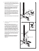
Orient the Support Bracket (33) as shown. Attach
the Support Bracket to the M10 x 67mm Carriage
Bolt (42) with an M10 Star Washer (92) and an
M10 Nylon Locknut (72).
Do not tighten the
Locknuts yet.
Attach the Support Bracket (33) to the Rear
Upright (3) with an M10 x 72mm Bolt (89), an M10
Washer (71), and an M10 Nylon Locknut (72).
Do
not tighten the Locknuts yet.
2
3
3
81
71
89
73
73
72
33
Slot
Hole
High Side
92
1
31
1
2
82
42
29
72
81
72
4
6
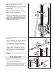
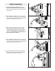
3. Press a 38mm Square Inner Cap (29) into the
Front Upright (4).
Attach the Front Upright (4) to the Base (1) with
the indicated M10 x 65mm Carriage Bolts (81)
and two M10 Nylon Locknuts (72).
Do not tight-
en the Locknuts yet.