
User's Manual
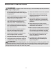

1.
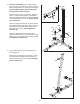
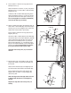
Attach a Base Cap (32) to the Stabilizer (2) with
two M4 Washers (75) and two M4 x 16mm Self-
tapping Screws (74).
Attach another Base Cap
to the Stabilizer in the same manner.
Insert two M8 x 67mm Carriage Bolts (82) and an
M10 x 67mm Carriage Bolt (42) up through the
Stabilizer (2). It may be helpful to place a piece
of tape over the bolt head to hold it in place.
5
1
42
32
2
82
75
74
32
Before beginning assembly, carefully read the
following information and instructions:
•
Assembly requires two people.
• To make assembly as easy as possible, we have
divided the assembly process into four stages.
The parts needed for each stage are found in
individual bags. Important: Wait until you begin
each stage to open the parts bag for that
stage. Place all parts of the weight system in a
cleared area and remove the packing materials.
Do not dispose of the packing materials until
assembly is completed.
• Tighten all parts as you assemble them, unless
instructed to do otherwise.
• As you assemble the weight system, make sure
all parts are oriented as shown in the drawings.
• For help identifying small parts, use the PART
IDENTIFICATION CHART.
The following tools (not included) are required
for assembly:
• Two adjustable wrenches
• One rubber mallet
• One standard screwdriver
• One Phillips screwdriver
• Lubricant, such as grease or petroleum jelly,
and soapy water.
Assembly will be more convenient if you have a
socket set, a set of open-end or closed-end
wrenches, or a set of ratchet wrenches.
Make Things Easier for Yourself
Everything in this manual is designed to ensure
that the weight system can be assembled suc-
cessfully by anyone. However, it is important to
realize that the versatile weight system has
many parts and that the assembly process will
take time. Most people find that by setting aside
plenty of time, assembly will go smoothly.
ASSEMBLY
Before you begin, make sure that you
have carefully read the instructions at the
top of this page.
Frame Assembly