
User's Manual
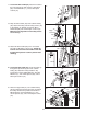
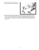
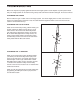

25. Locate the Low Cable (56). Route the Cable
through the Front Upright (4) and under a 90mm
Pulley (46). Attach the Pulley and two Pulley
Covers (49) inside the Upright with an M10 x
68mm Bolt (87), two M10 Washers (71), two
10mm Spacers (45), and an M10 Nylon Locknut
(72). Make sure the large tabs on the Pulley
Covers are in the indicated position.
Large
Tab
87
4
56
49
49
46
72
71
71
45
45
25
12
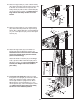
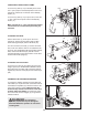
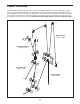
22. Route the High Cable (57) under a 90mm Pulley
(46). Attach the Pulley and two Pulley Covers (49)
t
o the first set of holes from the top of the two
Pulley Plates (50) with an M10 x 53mm Bolt (88)
a
nd an M10 Nylon Locknut (72). M
ake sure the
large tabs on the Pulley Covers are on the
bottom.
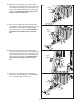
23. Route the High Cable (57) over a 90mm Pulley
(46). Attach the Pulley inside the Top Frame (6)
with an M10 x 68mm Bolt (87), two M10 Washers
(71), two 12mm Spacers (54), and an M10 Nylon
Locknut (72).
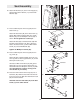
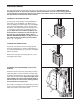
24. Attach the High Cable (57) to the Small “U”-
bracket (52) with an M8 Nylon Locknut (73).
Thread the Locknut onto the end of the Cable
so that two threads show past the Locknut
(see the inset drawing).
Attach the Small “U”-bracket (52) to the Weight
Tube (18) with an M8 x 45mm Bolt (96) and an
M8 Nylon Locknut (73). Do not overtighten the
Locknut; the Weight Tube must be able to
pivot freely.
24
57
96
52
73
73
18
22
5
0
Large
Tab
50
72
49
49
88
46
57
23
72
71
71
54
6
54
46
57
87
52
73
57