Model No.WEEVSY19230 Serial No. Write the serial number in the space above for reference. Serial Number Decal (under seat) QUESTIONS? As a manufacturer, we are committed to providing complete customer satisfaction. If you have questions, or if there are missing parts, please call: 08457 089 009 Or write: ICON Health & Fitness, Ltd. Unit 4 Revie Road Industrial Estate Revie Road Beeston Leeds, LS118JG UK email: csuk@iconeurope.
TABLE OF CONTENTS WARNING DECAL PLACEMENT . . . . . . . . . . . . . . . . . . . . . . . . . . . . . . . . . . . . . . . . . . . . . . . . . . . . . . . . . . . . . .2 IMPORTANT PRECAUTIONS . . . . . . . . . . . . . . . . . . . . . . . . . . . . . . . . . . . . . . . . . . . . . . . . . . . . . . . . . . . . . . . . .3 BEFORE YOU BEGIN . . . . . . . . . . . . . . . . . . . . . . . . . . . . . . . . . . . . . . . . . . . . . . . . . . . . . . . . . . . . . . . . . . . . . . .4 ASSEMBLY . . . . . . . . . . . .
IMPORTANT PRECAUTIONS WARNING : To reduce the risk of serious injury, read the following important precautions before using the weight system. 1. Read all instructions in this manual and in the accompanying literature before using the weight system. 2. It is the responsibility of the owner to ensure that all users of the weight system are adequately informed of all precautions. 3. The weight system is intended for home use only.
BEFORE YOU BEGIN Thank you for selecting the versatile WEIDER® 9015 weight system. The weight system offers a selection of weight stations designed to develop every major muscle group of the body. Whether your goal is to tone your body, build dramatic muscle size and strength, or improve your cardiovascular system, the weight system will help you to achieve the specific results you want. reading this manual, please call our Customer Service Department at 08457 089 009.
ASSEMBLY • Tighten all parts as you assemble them, unless instructed to do otherwise. Make Things Easier for Yourself Everything in this manual is designed to ensure that the weight system can be assembled successfully by anyone. However, it is important to realize that the versatile weight system has many parts and that the assembly process will take time. Most people find that by setting aside plenty of time, assembly will go smoothly.
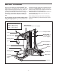
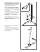
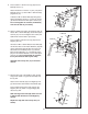
2. See the inset drawing. Press a 50mm Square Inner Cap (31) into the Base (1). Insert two M10 x 65mm Carriage Bolts (81) up through the Base. It may be helpful to place a piece of tape over the bolt head to hold it in place. 2 High Side 1 Orient the Rear Upright (3) as shown. Attach the Base (1) and the Rear Upright to the Stabilizer with the indicated M8 x 67mm Carriage Bolts (82) and two M8 Nylon Locknuts (73). Do not tighten the Locknuts yet. 3 81 31 Orient the Support Bracket (33) as shown.
4. Press two 38mm Square Bushings (35) into the Right Pedal (14); Attach a Pedal Cover (36) to the Pedal with two M4 x 16mm Self-tapping Screws (74) and two M4 Washers (75). 4 Lubricate the pedal axles on the Rear Upright (3). Slide the Right Pedal (14) onto the pedal axle. Make sure that the Pedal is on the correct side; the slotted brackets must be on the inside of the Pedal. 30 98 3 Hold a 25mm Retainer (98) and 25mm Round Outer Cap (30) against the right pedal axle.
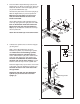
6. Insert two Weight Guides (5) into the Base (1). Make sure that the holes are on the top. 6 Holes 5 Slide two Weight Bumpers (44) onto the Weight Guides (5). Slide the nine Weights (16) onto the Weight Guides. Press the Weight Tube Bumper (17) into the Weight Tube (18). Insert the Weight Tube into the stack of Weights (16) as shown. 19 Lubricate Lubricate the indicated holes in the Top Weight (19) with grease. Slide the Top Weight onto the Weight Guides (5).
. Press a 50mm x 70mm Inner Cap (64) into the Butterfly Frame (11). 9 6 Attach the tethers on the two “L”-pins (100) to the Butterfly Frame (11) with an M4 x 16mm Self-tapping Screw (74). 64 83 72 Lubricate an M10 x 80mm Bolt (83) with grease. Attach the Butterfly Frame (11) to the Top Frame (6) with the Bolt and an M10 Nylon Locknut (72). Do not overtighten the Locknut; the Butterfly Arm must be able to pivot easily. Lubricate 74 11 10.
12 Cable Assembly 12. Locate the Butterfly Cable (55). Attach the Cable to the indicated Cable Pivot (58) with an M8 x 20mm Shoulder Bolt (93) and an M8 Nylon Locknut (73). 73 55 93 58 13. Wrap the Butterfly Cable (55) over a “V”-pulley (47). Attach the “V”-pulley and a Cable Trap (48) to the Front Upright (4) with an M10 x 60mm Bolt (95) and an M10 Nylon Locknut (72). 13 72 4 48 47 55 14. Wrap the Butterfly Cable (55) under a 90mm Pulley (46).
17. Locate the Short Cable (94). Attach the Cable to the Front Upright (4) with an M10 x 72mm Bolt (89), an M10 Washer (71), and an M10 Nylon Locknut (72). 17 4 71 94 89 72 18. Wrap the Short Cable (94) under a 90mm Pulley (46). Attach the Pulley and two Pulley Covers (49) to the Double “U”-bracket (51) with an M10 x 53mm Bolt (88) and an M10 Nylon Locknut (72). Make sure the large tabs on the Pulley Covers are on the top. 18 72 Large Tab 51 88 49 49 46 94 19.
22. Route the High Cable (57) under a 90mm Pulley (46). Attach the Pulley and two Pulley Covers (49) to the first set of holes from the top of the two Pulley Plates (50) with an M10 x 53mm Bolt (88) and an M10 Nylon Locknut (72). Make sure the large tabs on the Pulley Covers are on the bottom. 22 49 57 46 72 49 88 50 Large Tab 23. Route the High Cable (57) over a 90mm Pulley (46).
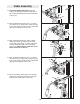
26. Route the Low Cable (56) over a 90mm Pulley (46). Attach the Pulley and two Pulley Covers (49) to the bottom set of holes in the “U”-bracket (53) with an M10 x 53mm Bolt (88) and an M10 Nylon Locknut (72). Make sure the large tabs on the Pulley Covers are on the top. 26 Large Tab 72 53 49 46 56 88 49 27. Wrap the Low Cable (56) under a 90mm Pulley (46). Attach the Pulley and two Pulley Covers (49) to the Base (1) with an M10 x 53mm Bolt (88) and an M10 Nylon Locknut (72).
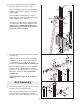
30 Seat Assembly 61 4 69 31. Press a 38mm Square Inner Cap (29) into the Seat Frame (7). 77 69 30. Attach the Backrest (61) to the Front Upright (3) with two M6 x 65mm Screws (77) and two M6 Washers (69). 77 31 62 Attach the Seat Plate (28) to the Seat Frame (7) with an M6 x 50mm Carriage Bolt (78), an M6 Washer (69), and an M6 Nylon Locknut (90) as shown. Do not tighten the Locknut yet. 78 28 76 29 Attach the Seat (62) to the Seat Plate (28) with two M6 x 16mm Screws (76).
34. Set the Seat Frame (7) on the pin on the Front Upright (4). Secure the Seat Frame with an M8 x 67mm Carriage Bolt (82) and the M8 Knob (43). 34 4 43 Pin 82 7 35. Make sure that all parts are properly tightened. The use of all remaining parts will be explained in ADJUSTMENT, beginning on the following page. Before using the weight system, pull each cable a few times to make sure that the cables move smoothly over the pulleys.
ADJUSTMENT The instructions below describe how each part of the weight system can be adjusted. IMPORTANT: When attaching the lat bar or nylon strap, make sure that the attachments are in the correct starting position for the exercise to be performed. If there is any slack in the cable or chain as an exercise is performed, the effectiveness of the exercise will be reduced. CHANGING THE WEIGHT SETTING To change the weight setting, insert the Weight Pin (20) under one of the Weights (16).
CONVERTING THE BUTTERFLY ARMS 100 To use the Fly Arms (9, 10) as butterfly arms, insert the “L”-pins (100) into the butterfly holes in the Front Upright (4) and the tab on the back of the Butterfly Frame (11). Butterfly 9 To use the Fly Arms (9, 10) as press arms, insert the “L”-pins (100) into the press holes in the Butterfly Frame (11). 100 4 Press 11 Make sure that the “L”-pins (100) are fully inserted into the same set of holes before performing any exercises.
WEIGHT RESISTANCE CHART The chart below shows the approximate weight resistance at each exercise station. “Top” refers to the 6 lb. top weight. The other numbers refer to the 12.5 lb. weight plates. Weight resistance shown for the butterfly arm station is for each butterfly arm. Note: The actual resistance at each station may vary due to differences in individual weight plates as well as friction between the cables, pulleys, and weight guides. WEIGHT HIGH PULLEY (lbs.) PRESS ARM (lbs.
TROUBLESHOOTING Make sure all parts are properly tightened each time the weight system is used. Replace any worn parts immediately. The weight system can be cleaned using a damp cloth and mild non-abrasive detergent. Do not use solvents. TIGHTENING THE CABLES Woven cable, the type of cable used on the weight system, can stretch slightly when it is first used. If there is slack in the cables before resistance is felt, the cables should be tightened.
CABLE DIAGRAM The cable diagram below shows the proper routing of the Butterfly Cable (55), the Low Cable (56), the High Cable (57), and the Short Cable (94). Use the diagram to make sure that the cables are assembled correctly. Use the diagrams to make sure that the cables and the cable traps have been assembled correctly. If the cables have not been correctly routed, the weight system will not function properly and damage may occur. The numbers show the correct route for each cable.
EXERCISE GUIDELINES THE FOUR BASIC TYPES OF WORKOUTS PERSONALIZING YOUR EXERCISE PROGRAM MUSCLE BUILDING To increase the size and strength of your muscles, push them close to their maximum capacity. Your muscles will continually adapt and grow as you progressively increase the intensity of your exercise. You can adjust the intensity level of an individual exercise in two ways: • by changing the amount of resistance used • by changing the number of repetitions or sets performed.
slowly as you stretch and do not bounce. Ease into each stretch gradually and go only as far as you can without strain. Stretching at the end of each workout is an effective way to increase flexibility. Rest for a short period of time after each set. The ideal resting periods are: • Rest for three minutes after each set for a muscle building workout. • Rest for one minute after each set for a toning workout. • Rest for 30 seconds after each set for a weight loss workout.
EXERCISE MONDAY WEIGHT SETS REPS WEIGHT SETS REPS WEIGHT SETS REPS Date: / / AEROBIC EXERCISE TUESDAY Date: / / WEDNESDAY EXERCISE Date: / / THURSDAY AEROBIC EXERCISE Date: / / EXERCISE FRIDAY Date: / / Make photocopies of this page for scheduling and recording your workouts.
ORDERING REPLACEMENT PARTS To order replacement parts, contact the ICON Health & Fitness, Ltd. office, or write: ICON Health & Fitness, Ltd.
REMOVE THIS PART LIST/EXPLODED DRAWING FROM THE MANUAL. 81 SAVE THIS PART LIST/EXPLODED DRAWING FOR FUTURE REFERENCE Note: Specifications are subject to change without notice. See the back cover of the user’s manual for information about ordering replacement parts.
PART LIST—Model No. WEEVSY19230 Key No. Qty.
84 27 66 66 65 84 72 27 73 29 97 79 66 8 28 90 62 11 71 99 55 41 82 10 24 67 59 73 58 84 25 80 69 70 43 60 71 59 60 83 86 23 100 55 73 66 7 72 64 58 93 23 86 100 78 76 69 29 71 72 60 71 72 72 60 27 59 26 13 25 80 26 24 27 9 59 85 34 56 72 49 71 29 47 71 54 63 71 95 71 45 72 57 46 46 72 61 72 31 49 84 65 72 85 93 74 41 87 71 77 87 94 49 77 47 94 49 72 68 46 71 31 72 71 46 71 49 88 49 1 87
This chart is provided to help you identify the small parts used in assembly. The number in parenthesis below each part refers to the key number of the part from the PART LIST in the centre of this manual. Important: Some parts may have been pre-assembled for shipping purposes. If you cannot find a part in the parts bags, check to see if it has been pre-assembled. Note: Assembly is divided into four stages: 1) frame assembly, 2) arm assembly, 3) cable assembly, and 4) seat assembly.
PART IDENTIFICATION CHART M4 x 16mm Self-tapping Screw (74) M6 Nylon Locknut (90) M6 x 16mm Screw (76) M8 Nylon Locknut (73) M8 x 20mm Button Head Bolt (84) M8 x 20mm Shoulder Bolt (93) M10 Nylon Locknut (72) M8 x 45mm Bolt (96) M4 Washer (75) M10 x 50mm Bolt (85) M6 x 53mm Screw (70) M6 Washer (69) M10 x 53mm Bolt (88) M6 x 50mm Carriage Bolt (78) M8 Washer (103) M8 x 57mm Bolt (79) M10 Large Washer (13) M10 Washer (71)
M10 x 60mm Bolt (95) M6 x 65mm Screw (77) M10 x 68mm Bolt (87) M10 x 65mm Carriage Bolt (81) M8 x 67mm Carriage Bolt (82) M10 x 67mm Carriage Bolt (42) M10 x 72mm Bolt (89) M10 x 80mm Bolt (83) M10 x 83mm Button Head Bolt (86) M10 x 153mm Bolt (91)
19mm Round Inner Cap (27) 38mm Square Inner Cap (29) 25mm Round Inner Cap (25) 40mm x 50mm Inner Cap (23) 25mm Round Outer Cap (30) 50mm Square Inner Cap (31) 16mm Round Outer Cap (38) 50mm x 70mm Inner Cap (64) 16mm Retainer (39) 25mm Retainer (98)