Model No. WEEVSY1909.0 Serial No. Write the serial number in the space above for future reference. USERʼS MANUAL Serial Number Decal (under seat) QUESTIONS? If you have questions, or if there are missing parts, please contact us: Call: 08457 089 009 From Ireland: 053 9236102 Website: www.iconsupport.eu E-mail: Visit www.iconsupport.eu Write: ICON Health & Fitness, Ltd.
TABLE OF CONTENTS WARNING DECAL PLACEMENT . . . . . . . . . . . . . . . . . . . . . . . . . . . . . . . . . . . . . . . . . . . . . . . . . . . . . . . . . . . . . 2 IMPORTANT PRECAUTIONS . . . . . . . . . . . . . . . . . . . . . . . . . . . . . . . . . . . . . . . . . . . . . . . . . . . . . . . . . . . . . . . . 3 BEFORE YOU BEGIN . . . . . . . . . . . . . . . . . . . . . . . . . . . . . . . . . . . . . . . . . . . . . . . . . . . . . . . . . . . . . . . . . . . . . . 4 PART IDENTIFICATION CHART . . . .
IMPORTANT PRECAUTIONS WARNING: To reduce the risk of serious injury, read all important precautions and instructions in this manual and all warnings on your weight system before using your weight system. ICON assumes no responsibility for personal injury or property damage sustained by or through the use of this product. 9. Keep hands and feet away from moving parts. 1. Before beginning any exercise program, consult your physician.
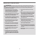
BEFORE YOU BEGIN after reading this manual, please see the front cover of this manual. To help us assist you, note the product model number and serial number before contacting us. The model number and the location of the serial number decal are shown on the front cover of this manual. Thank you for selecting the versatile WEIDER® 2990 I weight system. The weight system offers a selection of weight stations designed to develop every major muscle group of the body.
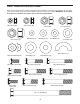
PART IDENTIFICATION CHART Refer to the drawings below to identify small parts used in assembly. The number in parentheses by each drawing is the key number of the part, from the PART LIST near the end of this manual. IMPORTANT: If you cannot find a part in the hardware kit, check to see if it has been preassembled.
ASSEMBLY To make assembly easier, carefully read the following information and instructions: • The following tools (not included) may be required for assembly: two adjustable wrenches • Assembly requires two persons. one rubber mallet • Because of its weight and size, the weight system should be assembled in the location where it will be used. Make sure that there is enough clearance to walk around the weight system as you assemble it.
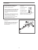
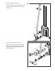
2. Slide the two Weight Bumpers (25) onto the Weight Guides (4), and insert the Weight Guides into the Short Base (6). 2 Attach the Weight Guides (4) to the Short Base (6) with two M10 x 25mm Screws (60) and two M10 Washers (73). 4 25 73 3. Orient the nine Weights (15) so that the pin holes are on the bottom of the Weights as shown. 25 60 6 73 3 Slide the Weights (15) onto the Weight Guides (4).
4. Orient the Weight Selector (7) and the Plastic Bushing (26) as shown. Slide the Plastic Bushing (26) onto the Weight Selector (7). Align the hole in the Plastic Bushing with the top hole in the Weight Selector. 4 4 Insert the Bushing Pin (28) into the Plastic Bushing (26) and the Weight Selector (7). Grease Insert the Weight Selector (7) into the nine Weights (15). 16 26 Apply some of the included grease to the indicated holes in the Top Weight (16).
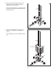
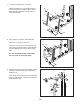
5. Orient the Upright (5) as shown. Attach the Upright (5) to the Long Base (1) with two M10 x 25mm Screws (60) and two M10 Washers (73). 5 5 60 60 73 73 1 6. Orient the Seat Frame (2) as shown. Attach the Seat Frame (2) and a Base Plate (83) to the Upright (5) with two M10 x 55mm Bolts (57), four M10 Washers (73), and two M10 Locknuts (68).
7. Orient the two Braces (21) as shown. Attach the Braces (21) to the Seat Frame (2) and the Long Base (1) with two M10 x 75mm Bolts (66), four M10 Washers (73), and two M10 Locknuts (68). 7 68 73 2 21 68 73 73 21 73 8. Apply grease to an M10 x 75mm Bolt (66). Orient the Leg Lever (3) as shown. 8 Attach the Leg Lever (3) to the bracket on the Seat Frame (2) with the M10 x 75mm Bolt (66), two M10 Washers (73), and an M10 Locknut (68). Do not overtighten the M10 Locknut (68).
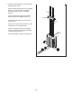
10. Apply grease to a 1/2" x 6 1/8" Bolt (64). Orient the Arm Frame (9) as shown. 10 Attach the Arm Frame (9) to the Top Frame (8) with the 1/2" x 6 1/8" Bolt (64), two 1/2" Washers (72), and a 1/2" Locknut (70). 64 Grease 72 Do not overtighten the 1/2" Locknut (70). The Arm Frame (9) must pivot easily. 11. Apply grease to an M8 x 42mm Screw (62). Hold the Lock Rod (46) inside the bracket on the Upright (5).
13. Identify the Left Arm (12), which is marked with an “L” sticker, and orient it as shown. Apply grease to the indicated location on the Left Arm (12). 13 56 Insert the Left Arm (12) into the Arm Frame (9). Attach the Left Arm with a 5/8" Locknut (75) and a 5/8" Washer (71). 13 Do not overtighten the 5/8" Locknut (75). The Left Arm (12) must pivot easily. Grease Then, press a 5/8" Dome Cap (56) onto the 5/8" Locknut (75). Repeat this step for the Right Arm (13). 14.
15. See the CABLE DIAGRAM on page 26 and identify the Arm Cable (51). Apply grease to an M10 x 35mm Bolt (59). 15 Grease Attach the end of the Arm Cable (51) to the Right Arm (13) with the M10 x 35mm Bolt (59), an M10 Washer (73), and an M10 Locknut (68). 13 Do not overtighten the M10 Locknut (68). The end of the Arm Cable (51) must pivot easily. 16. Route the Arm Cable (51) over a Pulley (42).
18. Route the Arm Cable (51) over a Pulley (42). Attach the Pulley (42) and two Cable Guides (52) to the left U-bracket (22) on the Upright (5) with an M10 x 50mm Bolt (58), two M10 Washers (73), and an M10 Locknut (68). 18 22 Make sure that the Cable Guides (52) are holding the Arm Cable (51) in the groove of the Pulley (42). 19. Apply grease to an M10 x 35mm Bolt (59).
21. Route the High Cable (53) through the center bracket on the Top Frame (8). Attach a Pulley (42) and two Cable Guides (52) to the center bracket on the Top Frame (8) with an M10 x 50mm Bolt (58), two M10 Washers (73), and an M10 Locknut (68). 21 68 Attach a Pulley (42) and two Cable Guides (52) to the rear bracket on the Top Frame (8) with an M10 x 50mm Bolt (58), two M10 Washers (73), and an M10 Locknut (68).
24. Locate the High Cable (53) hanging between the center and rear brackets on the Top Frame (8). 24 8 Set a Pulley (42) on the High Cable (53). Attach the Pulley (42) and two Cable Guides (52) between the top holes in the two Pulley Plates (23) with an M10 x 50mm Bolt (58), two M10 Washers (73), and an M10 Locknut (68). 68 Make sure that the Cable Guides (52) are holding the High Cable (53) in the groove of the Pulley (42). 25. See the CABLE DIAGRAM on page 26 and identify the Low Cable (54).
27. Route the Low Cable (54) over a Pulley (42). Attach the Pulley (42) and two Cable Guides (52) to the Double U-bracket (24) with an M10 x 50mm Bolt (58), two M10 Washers (73), and an M10 Locknut (68). 27 68 73 Make sure that the Cable Guides (52) are holding the Low Cable (54) in the groove of the Pulley (42). 28. Route the Low Cable (54) under a Pulley (42).
30. Orient the Backrest (11) so that the wide end is facing downward. Attach the Backrest (11) to the Upright (5) with two M8 x 42mm Screws (62) and two M8 Washers (74). 30 5 11 74 74 Wide End 31. Orient the Seat (10) so that the wide end is in the indicated location. Attach the Seat (10) to the Seat Frame (2) with four M8 x 16mm Screws (63) and four M8 Washers (74).
32. Identify the Long Pad Tube (19) and the Short Pad Tube (20). Insert the Long Pad Tube (19) through the bracket on the Seat Frame (2). Slide two Small Foam Pads (39) onto the ends of the Long Pad Tube. 32 Insert the Short Pad Tube (20) through the Leg Lever (3). Slide two Small Foam Pads (39) onto the ends of the Short Pad Tube. 39 2 39 19 3 33. Slide the upper end of a Shroud (29) onto a Shroud Bracket (30). Then, slide the lower end of the Shroud (29) onto a Shroud Bracket (30).
34. Have a second person hold the Shrouds (29) and the upper Shroud Brackets (30) around the rear of the Top Frame (8). 34 74 65 Attach the front of each upper Shroud Bracket (30) to the Shroud Plate (82) with an M8 x 20mm Screw (65) and an M8 Washer (74). 29 30 8 82 74 65 30 29 4 35. Insert the hook on the J-bolt (80) into the center hole in the Shroud Plate (82). Then, insert the J-bolt (80) upward through the Top Frame (8).
36. Attach the lower Shroud Brackets (30) to the Short Base (6) with four M8 x 20mm Screws (65) and four M8 Washers (74). 36 65 74 30 65 74 30 6 74 65 37. Make sure that all parts are properly tightened. The use of the remaining parts will be explained in ADJUSTMENT, beginning on page 22. Before using the weight system, pull each cable a few times to make sure that the cables move smoothly around the pulleys. If one of the cables does not move smoothly, find and correct the problem.
ADJUSTMENT This section explains how to adjust the weight system. See the EXERCISE GUIDELINES on page 27 for important information about how to get the most benefit from your exercise program. Make sure all parts are properly tightened each time the weight system is used. Replace any worn parts immediately. The weight system can be cleaned with a damp cloth and a mild, non-abrasive detergent; do not use solvents.
CONVERTING THE ARMS To use the Arms (12, 13) as butterfly arms, pivot the Lock Rod (46) into the groove in the Arm Frame (9) and tighten the Lock Knob (45). 46 To use the Arms (12, 13) as press arms, loosen the Lock Knob (45) and pivot the Lock Rod (46) out of the groove in the Arm Frame (9).
WEIGHT RESISTANCE CHART The chart below shows the approximate weight resistance at each exercise station. The numbers in the left column refer to the 11-lb. weights. Note: The actual resistance at each station may vary due to differences in individual weights as well as friction between the cables, pulleys, and weight guides. WEIGHT 0 1 2 3 4 5 6 7 8 9 HIGH PULLEY (lbs.) 14.7 27.2 39.5 50.6 62.1 74.3 86.1 97.5 112.4 122.8 BUTTERFLY ARM (lbs.) 13.2 21.8 28.5 38.2 42.8 48.7 56.3 63.4 72.7 82.5 Note: 1 lb.
MAINTENANCE Make sure that all parts are properly tightened each time the weight system is used. Replace any worn parts immediately. The weight system can be cleaned with a damp cloth and a mild, non-abrasive detergent. Do not use solvents to clean the weight system. TIGHTENING THE CABLES Woven cable, the type of cable used on the weight system, can stretch slightly when it is first used. If there is slack in the cables before resistance is felt, the cables should be tightened.
CABLE DIAGRAM The diagram below shows the proper routing of the cables. The numbers in each drawing show the proper route for that cable. Use the diagram to make sure that the cables and the cable guides are assembled correctly. If the cables are not assembled correctly, the weight system will not function properly and damage may occur. High Cable (53) Length: 113 in. (287 cm) Arm Cable (51) Length: 102 in. (260 cm) 1 1 4 2 3 3 5 2 Low Cable (54) Length: 142 in.
EXERCISE GUIDELINES FOUR TYPES OF STRENGTH WORKOUTS Note: A “repetition” is one complete cycle of an exercise, such as one sit-up. A “set” is a series of repetitions. Muscle Building—Work your muscles near their maximum capacity and progressively increase the intensity of your exercise. Adjust the intensity level of an individual exercise as follows: • Change the amount of resistance used. • Change the number of repetitions or sets performed.
EXERCISE LOG Make copies of this page, and use the copies to schedule and record your strength and aerobic workouts. Scheduling and recording your workouts will help you to make exercise a regular and enjoyable part of your life. Strength Date: Exercise 1. Lbs. Sets Reps 2. 8. 4. Strength Date: 9. 5. 10. Exercise Exercise 1. Time Lbs. Sets Reps 2. Strength Date: Exercise 1. 6. 9. 5. Exercise Lbs. Sets Reps Exercise 8. 4. Aerobic Date: Distance Speed 7. 3. 10. Time Lbs.
PART LIST—Model No. WEEVSY1909.0 Key No. Qty.
EXPLODED DRAWING A—Model No. WEEVSY1909.
EXPLODED DRAWING B—Model No. WEEVSY1909.
ORDERING REPLACEMENT PARTS To order replacement parts, please see the front cover of this manual. To help us assist you, be prepared to provide the following information when contacting us: • the model number and serial number of the product (see the front cover of this manual) • the name of the product (see the front cover of this manual) • the key number and description of the replacement part(s) (see the PART LIST and the EXPLODED DRAWING near the end of this manual) Part No.