
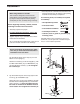
User's Manual
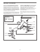
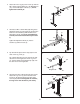
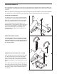

7. Tap two 19mm Round Inner Caps (9) into each
Long Pad Tube (10). Slide the Pad Tubes into the
holes in the Leg Lever (4). Slide two Long Foam
Pads (23) onto each Pad Tube.
8. Tap two 25mm Square Inner Caps (35) into each
Backrest Tube (5).
Attach each Backrest Tube (5) to the Backrest (6)
with two M6 x 38mm Screws (30) and two M6
Washers (26).
Do not tighten the Screws yet.
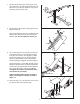
9. Tap a 19mm Round Inner Cap (9) into each end
of the Support Rod (7). Insert the Support Rod
through a set of holes in the Uprights (1). Make
sure that the locking pin is on the side shown.
Rotate the Support Rod to the locked position,
with the locking pin wrapped around the Upright.
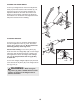
Lubricate the M10 x 137mm Bolt (36) with grease.
Attach the Backrest
Tubes (5) to the welded tube
on the Frame (2) with the Bolt, two M10 Washers
(34), and an M10 Nylon Locknut (33). Do not
overtighten the Locknut; the Backrest T
ubes
must be able to pivot easily.
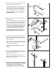
T
ighten the M6 x 38mm Screws (30) used in
step 8, and the Nylon Locknuts (17) used in
steps 1–3.
10. Attach the Seat (11) to the brackets on the Frame
(2) with four M6 x 16mm Screws (29).
9
10
10
9
4
23
23
7
7
8
5
30
26
26
30
6
35
35
9
9
9
34
5
36
7
1
2
Welded Tube
1
Locking
Pin
33
34
10
11
29
2