
User's Manual


6
Grease
9
9
5
45
4
7
42
Grease
Grease
1
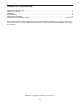
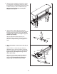
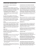
4. Note: The backrest is not shown in this step for
clarity
.
Grease an M10 x 175mm Bolt (42). Attach the
Adjustment Leg (5) to the Top Frame (1) with the
Bolt and an M10 Nylon Locknut (45). Do not over-
tighten the Bolt; the Adjustment Leg must be
able to pivot easily.
Grease two M10 x 20mm Screws (9). Attach the
Support Leg (7) to the Top Frame (1) with the
Screws. Do not overtighten the Screws; the
Support Leg must be able to pivot easily.
2
4
3
39
51
39
51
35
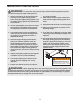
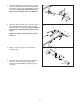
2. Make sure that the Bungee Cords (35) are resting
in the brackets on the Backrest Frame (3). Attach
t
he Backrest (4) to the Backrest Frame with four M6
x 38mm Screws (51) and four M6 Washers (39).
M
ake sure that the Backrest is holding the
Bungee Cords in place.
Grease
7
5
3
48
58
45
43
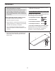
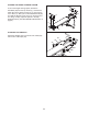
3. Grease an M10 x 80mm Bolt (43). Attach the
Support Leg (7) to the Adjustment Bracket (48) with
the Bolt and an M10 Nylon Locknut (45). Do not
overtighten the Locknut; the Support Leg must
be able to pivot easily.
Slide the Adjustment Bracket (48) onto the
Adjustment Leg (5). Engage the indicated Knob
(58) into the Adjustment Leg, and fully tighten the
Knob.