Model No. WEEMSY18220 Serial No. USER'S MANUAL Write the serial number in the space above for future reference. Serial Number Decal (Under Seat) QUESTIONS? As a manufacturer, we are committed to providing complete customer satisfaction. If you have questions, or if there are missing parts, please call: 08457 089 009 Or write: ICON Health & Fitness, Ltd. Unit 4 Revie Road Industrial Estate Revie Road Beeston Leeds, LS118JG UK email: csuk@iconeurope.
TABLE OF CONTENTS IMPORTANT PRECAUTIONS . . . . . . . . . . . . . . . . . . . . . . . . . . . . . . . . . . . . . . . . . . . . . . . . . . . . . . . . . . . . . . . . 3 BEFORE YOU BEGIN . . . . . . . . . . . . . . . . . . . . . . . . . . . . . . . . . . . . . . . . . . . . . . . . . . . . . . . . . . . . . . . . . . . . . . 4 ASSEMBLY . . . . . . . . . . . . . . . . . . . . . . . . . . . . . . . . . . . . . . . . . . . . . . . . . . . . . . . . . . . . . . . . . . . . . . . . . . . . . . 5 ADJUSTMENTS . .
IMPORTANT PRECAUTIONS WARNING: To reduce the risk of serious injury, read the following important precautions before using the weight system. 1. Read all instructions in this manual and in the accompanying literature before using the weight system. Use the weight system only as described in this manual. 12. Make sure that the cables remain on the pulleys at all times. If the cables bind whilst you are exercising, stop immediately and make sure that the cables are on all of the pulleys. 2.
BEFORE YOU BEGIN Thank you for selecting the versatile WEIDER® 8950 weight system. The WEIDER® 8950 weight system offers a selection of weight stations designed to develop every major muscle group of the body. Whether your goal is to tone your body, build dramatic muscle size and strength, or improve your cardiovascular system, the WEIDER® 8950 weight system will help you to achieve the results you want. questions, please call our Customer Service Department at 08457 089 009.
ASSEMBLY • As you assemble the weight system, make sure all parts are oriented as shown in the drawings. Make Things Easier for Yourself Everything in this manual is designed to ensure that the weight system can be assembled successfully by anyone. However, it is important to realise that the versatile weight system has many parts and that the assembly process will take time. Most people find that by setting aside plenty of time, assembly will go smoothly.
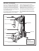
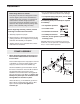
2. Attach the Upright (3) to the Base (1) with the two M8 x 63mm Carriage Bolts (58) and two M8 Nylon Locknuts (69). Do not tighten the Locknuts yet. 2 66 39 71 Press a 25mm x 50mm Inner Cap (25) into the tube on the Upright (3). Attach the Press Frame Lock (39) to the Upright with an M8 x 63mm Bolt (66), two M8 Washers (71), and an M8 Nylon Locknut (69). Do not overtighten the Nylon Locknut; the Press Frame Lock must be able to pivot easily. 69 25 71 3 69 1 58 3.
4. Slide the eight Weights (15) onto the Weight Guides (10), with the slot for the Weight Pin (not shown) on the bottom and on the side away from the Upright (3). 4 10 14 Insert the Weight Tube Bumper (13) into the bottom of the Weight Tube (12). Insert the Weight Tube into the Weights (15). 12 Slide the Top Weight (14) onto the Weight Guides (10). 3 13 15 5. Press a 50mm Square Inner Cap (26) into the Top Frame (4).
7 ARM ASSEMBLY Lubricate 74 7. Press two 45mm Square Inner Caps (24) into the Leg Lever (9). Lubricate an M10 x 73mm Bolt (74) with grease. Attach the Leg Lever (9) to the Seat Frame (8) with the Bolt and an M10 Nylon Locknut (68). Make sure the warning decal is in the indicated position. Do not overtighten the Locknut; the Leg Lever must be able to pivot easily. 8 24 Warning Decal 68 9 24 8. Press two 25mm x 50mm Inner Cap (25) into the top of the Press Frame (5).
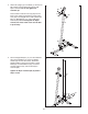
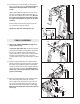
10. Insert the post on the Left Arm (7) through the hole in the Press Frame (5). Be sure the Arm is behind the indicated bracket on the Press Frame. 10 27 Slot 29 72 6 Slide a 25mm Washer (29) over the post on the Left Arm (7). Attach an M6 x 43mm Bolt (61) to the post with an M6 Nylon Locknut (72). Be sure the Locknut and the head of the Bolt are over the edge of the Washer, as shown in the inset drawing. 5 Bracket 7 61 Press a 25mm Round Outer Cap (27) onto the top of the post on the Left Arm (7).
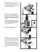
14. Wrap the High Cable (50) over a 90mm Pulley (34). Attach the Pulley and a pair of Pulley Covers (35) to the bracket on the Top Frame (4) with an M10 x 52mm Bolt (52) and an M10 Nylon Locknut (68). Make sure the small tabs on the Pulley Covers are on bottom. 14 52 4 68 34 35 35 50 15. Attach the end of the High Cable (50) to the Small “U”-bracket (11) with an M8 Washer (71) and an M8 Nylon Locknut (69).
18. Wrap the Press Cable (49) under a 90mm Pulley (34). Attach the Pulley and a pair of Pulley Covers (35) to the Offset Double “U”-bracket (42) with an M10 x 52mm Bolt (52) and an M10 Nylon Locknut (68). Make sure the small tabs on the Pulley Covers are on top. 18 49 35 34 35 52 68 19. Attach the Pulley Arm (38) to the Upright (3) with an M10 x 78mm Bolt (54) and an M10 Nylon Locknut (68). Do not overtighten the Locknut; the Pulley Arm must be able to pivot easily.
22. Wrap the Short Cable (47) over a 90mm Pulley (34). Attach the Pulley and a pair of Pulley Covers (35) to the Offset Double “U”-bracket (42) with an M10 x 52mm Bolt (52) and an M10 Nylon Locknut (68). Make sure the small tabs on the Pulley Covers are on bottom. 22 52 42 68 34 35 47 23. Attach the end of the Short Cable (47) to the “U”bracket (43) with an M8 Washer (71) and an M8 Nylon Locknut (69).
26. Wrap the Low Cable (48) under a 90mm Pulley (34). Attach the Pulley and a pair of Pulley Covers (35) to the bracket on the Base (1) with an M10 x 52mm Bolt (52) and an M10 Nylon Locknut (68). Make sure the small tabs on the Pulley Covers are on top. 26 48 35 34 52 35 68 1 27. Route the Low Cable (48) over a 90mm Pulley (34). Attach the Pulley and a pair of Pulley Covers (35) to the lower set of holes in the “U”bracket (43) with an M10 x 52mm Bolt (52) and an M10 Nylon Locknut (68).
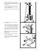
30 SEAT ASSEMBLY 30. Attach the Backrest (18) to the Upright (3) with two M6 x 63mm Screws (67) and two M6 Washers (73). 73 67 73 67 18 3 31. Attach the Seat (19), oriented as shown, to the Seat Frame (8) with four M6 x 16mm Screws (40). 31 19 Narrow End 8 40 32. Slide a Pad Tube (45) through the hole in the Seat Frame (8). Slide two Round Pads (21) onto the ends of the Pad Tube. Press two 19mm Round Inner Caps (22) into the ends of the Pad Tube.
ADJUSTMENTS This section explains how to adjust the weight system. Refer to the accompanying exercise guide to see the correct form for each exercise. Make sure all parts are properly tightened each time the weight system is used. Replace any worn parts immediately. The weight system can be cleaned with a damp cloth and a mild, non-abrasive detergent. Do not use solvents. ATTACHING THE LAT BAR Attach the Lat Bar (31) to the High Cable (50) with a Cable Clip (33).
WEIGHT RESISTANCE CHART The chart below shows the approximate weight resistance at each exercise station. “Top” refers to the 6-lb. top weight. The other numbers refer to the 12.5-lb. weight plates. Weight resistance shown for the butterfly arm station is for each butterfly arm. Note: The actual resistance at each station may vary due to differences in individual weight plates as well as friction between the cables, pulleys, and weight guides. WEIGHT HIGH PULLEY (lbs.) PRESS ARM (lbs.
CABLE DIAGRAMS The cable diagrams below show the proper routing of the Short Cable (47), the Low Cable (48), the Press Cable (49), and the High Cable (50). Use the diagrams to make sure that the cables have been assembled correctly. If the cables have not been correctly routed, the weight system will not function properly and damage may occur. The numbers show the correct route for each cable.
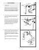
TROUBLESHOOTING AND MAINTENANCE TIGHTENING THE CABLES Woven cable, the type of cable used on the weight system, can stretch slightly when it is first used. If there is slack in the cables before resistance is felt, the cables should be tightened. 44 52 Slack can be removed by moving a 90mm Pulley (not shown) and a pair of Pulley Covers (35) to a set of holes closer to the centre of the two Pulley Plates (44).
NOTES 19
ORDERING REPLACEMENT PARTS To order replacement parts, contact the ICON Health & Fitness, Ltd. office, or write: ICON Health & Fitness, Ltd.
This chart is provided to help you identify the small parts used in assembly. The number in parenthesis below each part refers to the key number of the part from the PART LIST in the centre of this manual. Important: Some parts may have been pre-assembled for shipping purposes. If you cannot find a part in the parts bags, check to see if it has been pre-assembled. Note: The assembly is divided into four stages: 1) frame assembly, 2) arm assembly, 3) cable assembly, 4) seat assembly.
PART IDENTIFICATION CHART—Model No. WEEMSY18220 M10 Nylon Locknut (68) M8 Nylon Locknut (69) 19mm Round Inner Cap (22) M6 Nylon Locknut (72) M10 x 22mm Spacer (51) 25mm Round Outer Cap (27) M10 x 12.
M6 x 63mm Screw (67) M8 x 63mm Bolt (66) M6 x 58mm Bolt (65) M8 x 64mm Shoulder Bolt (56) M10 x 65mm Bolt (55) M10 x 52mm Bolt (52) M6 Washer (73) M8 x 63mm Carriage Bolt (58) M10 x 50mm Bolt (53) M8 x 68mm Bolt (63) M8 x 45mm Bolt (60) M8 Washer (71) M10 x 65mm Carriage Bolt (59) M6 x 43mm Bolt (61) M10 x 70mm Bolt (57) M6 x 16mm Screw (40) M10 Washer (70) M10 x 73mm Bolt (74) M10 x 78mm Bolt (54) 25mm Washer (29) M10 x 100mm Bolt (46) M10 x 125mm Bolt (64) M10 x 155mm Bolt (62)
REMOVE THIS PART LIST/EXPLODED DRAWING FROM THE MANUAL.
PART LIST—Model No. WEEMSY18220 Key No. Qty.
65 23 73 73 6 24 49 20 61 26 24 70 65 27 29 5 28 64 22 23 61 72 73 68 56 21 72 28 29 27 70 73 25 24 48 22 23 74 24 7 49 26 30 68 45 71 69 9 24 21 20 26 45 32 21 8 57 40 31 22 33 40 70 55 50 37 19 52 68 22 32 68 53 70 21 37 34 35 36 34 68 52 26 35 34 35 46 68 35 38 68 4 34 70 18 34 68 54 71 69 26 35 25 71 66 69 39 63 67 68 70 69 3 1 73 67 73 69 35 35 55 35 68 69 68 71 47 70 68 47 57 68 35