Model No. WEEMBE39221 Serial No. Write the serial number in the space above for reference. USER’S MANUAL Serial Number Decal (under seat) QUESTIONS? As a manufacturer, we are committed to providing complete customer satisfaction. If you have questions, or if there are missing or damaged parts, please call: 08457 089 009 Or write: ICON Health & Fitness, Ltd. Unit 4 Revie Road Industrial Estate Revie Road Beeston Leeds LS11 8JG UK csuk@iconeurope.
TABLE OF CONTENTS WARNING DECAL PLACEMENT . . . . . . . . . . . . . . . . . . . . . . . . . . . . . . . . . . . . . . . . . . . . . . . . . . . . . . . . . . . . . 2 IMPORTANT PRECAUTIONS . . . . . . . . . . . . . . . . . . . . . . . . . . . . . . . . . . . . . . . . . . . . . . . . . . . . . . . . . . . . . . . . 3 BEFORE YOU BEGIN . . . . . . . . . . . . . . . . . . . . . . . . . . . . . . . . . . . . . . . . . . . . . . . . . . . . . . . . . . . . . . . . . . . . . . 4 ASSEMBLY . . . . . . . . . . . . .
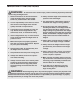
IMPORTANT PRECAUTIONS WARNING: To reduce the risk of serious injury, read the following important precautions before using the weight bench. 10. Always set both weight rests and both safety spotters at the same height. 1. Read all instructions in this manual before using the weight bench. Use the weight bench only as described in this manual. 11. The weight bench is designed to support a maximum user weight of 115 kg (250 lbs.). 2.
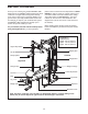
BEFORE YOU BEGIN please call our Customer Service Department at 08457 089 009. To help us assist you, please note the product model number and serial number before calling. The model number is WEEMBE39221. The serial number can be found on a decal attached to the weight bench (see the front cover of this manual for the location). Thank you for selecting the versatile WEIDER® 9000 weight bench.
ASSEMBLY • As you assemble the weight bench, make sure all parts are oriented as shown in the drawings. Make Things Easier for Yourself Everything in this manual is designed to ensure that the weight bench can be assembled successfully by anyone. However, it is important to realize that the versatile weight bench has many parts and that the assembly process will take time. Most people find that by setting aside plenty of time, assembly will go smoothly.
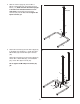
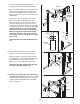
2. Slide the Centre Upright (5) onto the M10 x 60mm Carriage Bolts (50) in the Right and Left Bases (1, 2). Make sure that the Centre Upright is turned so the indicated bracket is on the side shown. Hand tighten two M10 Nylon Locknuts (49) onto the Bolts. Do not tighten the Nylon Locknuts yet. 2 Bracket 5 49 49 50 1 2 3. Attach the Foot Plate (9) and the Rear Upright (6) to the Right and Left Bases (1, 2) with two M10 x 68mm Bolts (46) and two M10 Nylon Locknuts (49).
4. Attach one of the Uprights (3) to the Right Base (1) with four M10 x 68mm Bolts (46), two Support Plates (14), and four M10 Nylon Locknuts (49). Do not tighten the Nylon Locknuts yet. 4 Repeat this step with the other Upright (not shown) and the Left Base (not shown). 3 49 49 14 1 14 46 5. Press a 50mm Square Inner Cap (43) into the top of the right Upright (3). 5 16 Slide a Safety Spotter (15) onto the right Upright (3) and engage the Knob (17) into the lowest adjustment hole in the Upright.
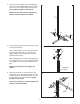
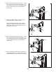
7. Slide the Carriage Stop (19) onto the Rear Upright (6). Make sure that the Carriage Stop is oriented so the Carriage Stop Bushing (20) and the indicated hole are in the positions shown. Attach the Carriage Stop to the hole near the bottom of the Rear Upright with an M8 x 70mm Bolt (58) and an M8 Nylon Locknut (48). 7 45 10 45 61 Press two 25mm Round Inner Caps (45) into the tube on the Weight Carriage (10). Insert an M10 x 19mm Bolt (61) into the bracket on the Weight Carriage.
11. Identify the Right and Left Butterfly Arms (11, 12) by noting the positions of the welded brackets. 11 Bracket 8 11 Press two 45mm Square Inner Caps (42) into the ends of the Left Butterfly Arm (12). Wet the bottom end of the Butterfly Arm with soapy water. Slide a Large Foam Pad (18) onto the end of the Butterfly Arm. Lubricate Axle 42 Welded Bracket 35 Lubricate the axles on the Top Frame (8) with grease.
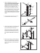
14. Wrap the Butterfly Cable (32) around a “V”-Pulley (25). Attach the Pulley and a Large Cable Trap (27) to the bracket on the Centre Upright (5) with an M10 x 60mm Bolt (47) and an M10 Nylon Locknut (49). 14 49 Bracket 27 25 47 32 5 15. Remove the 90mm Pulleys (24) from the preassembled Double “U”-Bracket (29). 15 Wrap the Butterfly Cable (32) under a 90mm Pulley (24). Attach the Pulley to the Double “U”Bracket with an M10 x 45mm Bolt (57) and an M10 Nylon Locknut (49). 24 32 49 57 29 16.
18. Identify the High Cable (31), which is the shorter of the two remaining cables. Route the eyelet end of the Cable up through the indicated hole in the Top Frame (8). 18 49 24 52 Wrap the High Cable (31) around a 90mm Pulley (24). Attach the Pulley inside of the Top Frame (8) with an M10 x 65mm Bolt (54), two 15mm x 13mm Spacers (39), two M10 Washers (52), and an M10 Nylon Locknut (49). 52 8 39 39 54 31 19. Route the High Cable (31) down through the indicated hole in the Top Frame (8).
22. Attach the High Cable (31) to the M10 x 19mm Bolt (not shown) in the bracket on the Weight Carriage (10) with an M10 Nylon Locknut (49). 22 31 49 Bracket 10 23. Locate the Low Cable (33). Route the eyelet end of the Cable through the hole in the Foot Plate (9) and through the Centre Upright (5). 23 5 49 52 39 24 Wrap the Low Cable (33) under a 90mm Pulley (24).
26. Wrap the Low Cable (33) around a 90mm Pulley (24). Attach the Pulley and a Cable Trap (26) to the second hole from the bottom of the two Pulley Plates (28) with an M10 x 45mm Bolt (57) and an M10 Nylon Locknut (49). 26 28 49 57 26 24 33 27. Attach the end of the Low Cable (33) inside the hole in the Rear Upright (6) with an M10 x 65mm Bolt (54), two M10 Washers (52) and an M10 Nylon Locknut (49). 27 33 6 52 49 28.
29 Bench Assembly 49 29. Press two 51mm x 76mm Outer Caps (79) onto the Stabiliser (62). Attach the Stabiliser to the Bench Frame (63) with two M10 x 60mm Carriage Bolts (50) and two M10 Nylon Locknuts (49). 63 62 79 50 30. Press three 50mm Square Inner Caps (43) into the Front Leg (64). 79 30 43 Attach the Front Leg (64) to the Bench Frame (63) with two M10 x 65mm Bolts (54), two M10 Washers (52), and two M10 Nylon Locknuts (49). 49 63 52 49 54 64 43 31.
33. Orient the Seat (70) with the wide end on the side shown. Attach the Seat to the Bench Frame (63) with four M6 x 16mm Bolts (80). 33 70 Wide End 63 80 80 34. Press three 45mm Square Inner Caps (42) into the Leg Lever (66). 34 42 Attach the Weight Tube (65) to the Leg Lever (66) with an M8 x 58mm Bolt (41), two M8 Washers (53), a 13mm x 10mm Spacer (75), and an M8 Nylon Locknut (48). 66 42 76 75 41 53 Press a 25mm Round Inner Cap (45) into the indicated end of the Weight Tube (65).
37. Attach the Curl Pad (84) to the Curl Post (83) with two M6 x 16mm Bolts (80). 37 84 83 38. Make sure that all parts have been properly tightened. The use of the remaining parts will be explained in ADJUSTMENTS, below. 80 ADJUSTMENTS This section explains how to adjust the weight bench. See the EXERCISE GUIDELINES on page 22 for important information about how to get the most benefit from your exercise program. Also, refer to the accompanying exercise guide to see the correct form for each exercise.
ATTACHING THE LAT BAR TO THE HIGH PULLEY STATION OR THE LOW PULLEY STATION To use the high or low pulley station, attach the Lat Bar (73) to the High Cable (31) or the Low Cable (not shown) using a Cable Clip (30). The Row Bar (not shown) can be attached in the same manner. 31 WARNING: Always remove the Lat Bar (73) when performing an exercise that does not require the use of the Lat Bar.
USING THE CURL PAD 84 Remove the 50mm Square Inner Cap (43) from the Front Leg (64). Align a hole in the Curl Post (83) with the hole in the Front Leg (64). Secure the Curl Post with the Curl Knob (4). Be sure the Knob is fully tightened. 83 4 43 Note: When not using the Curl Pad (84), store it away from the weight bench. 64 ADJUSTING THE BACKREST The Bench Backrest (69) can be used in a decline position, a level position, or either of two incline positions.
WEIGHT RESISTANCE CHART This chart shows the approximate weight resistance at each weight station. The column labeled “WEIGHT” refers to the amount of weight, in pounds, placed on the weight carriage. The weight resistance shown for the butterfly arm station is for each butterfly arm. Note: The actual resistance at each station may vary due to friction between the cables, pulleys, and weight carriage. WEIGHT (lbs.) BUTTERFLY ARM (lbs.) LOW PULLEY (lbs.) HIGH PULLEY (lbs.
CABLE DIAGRAMS The cable diagrams below show the proper routing of the High Cable (31), the Butterfly Cable (32), and the Low Cable (33). Use the diagram to make sure that the cables and the cable traps have been assembled correctly. If the cables have not been correctly routed, the weight bench will not function properly and damage may occur. The numbers show the correct route for each cable. Make sure that the cable traps do not touch or bind the cables.
TROUBLESHOOTING AND MAINTENANCE Make sure all parts are properly tightened each time you use the weight bench. Replace any worn parts immediately. The weight bench can be cleaned using a damp cloth and mild non-abrasive detergent. Do not use solvents. TIGHTENING THE CABLES Woven cable, the type of cable used on the weight rack, can stretch slightly when it is first used.
EXERCISE GUIDELINES THE FOUR BASIC TYPES OF WORKOUTS PERSONALISING YOUR EXERCISE PROGRAM Muscle Building To increase the size and strength of your muscles, push them close to their maximum capacity. Your muscles will continually adapt and grow as you progressively increase the intensity of your exercise. You can adjust the intensity level of an individual exercise in two ways: • by changing the amount of weight used • by changing the number of repetitions or sets performed.
slowly as you stretch and do not bounce. Ease into each stretch gradually and go only as far as you can without strain. Stretching at the end of each workout is an effective way to increase flexibility. Rest for a short period of time after each set. The ideal resting periods are: • Rest for three minutes after each set for a muscle building workout. • Rest for one minute after each set for a toning workout. • Rest for 30 seconds after each set for a weight loss workout.
ORDERING REPLACEMENT PARTS If you encounter any problems with this product, or if you need to order replacement parts, contact the ICON Health & Fitness, Ltd. office, or write: ICON Health & Fitness, Ltd.
PART IDENTIFICATION CHART Refer to the drawings below to identify small parts used in assembly. The number in parentheses by each drawing is the key number of the part, from the PART LIST in the centre of this manual. Note: Some small parts may have been pre-attached. If a part is not in the parts bag, check to see if it has been pre-attached.
19mm Round Inner Cap (81) 51mm x 76mm Outer Cap (79) 25mm Round Inner Cap (45) 25mm x 50mm Inner Cap (82) 13mm x 12mm Spacer (38) 50mm Square Inner Cap (43) 15mm x 8mm Spacer (55) 13mm x 10mm Spacer (75) 15mm x 13mm Spacer (39) 45mm Square Inner Cap (42) 15mm x 10mm Spacer (40) M10 x 180mm Bolt (78) 1” Retainer (35)
PART LIST—Model No. WEEMBE39221 Key No. Qty.
EXPLODED DRAWING—Model No.