
User's Manual

8
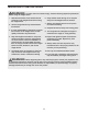
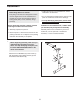
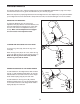
8. Remove the indicated M10 Nylon Locknut (44)
from the Right Adjustment Bracket (27). Attach
t
he Right “L”-bar (18) to the Right Adjustment
Bracket with the M10 Nylon Locknut.
Do not
o
vertighten the Nylon Locknut; the “L”-bar
must be able to pivot easily.
Repeat this step with the Left “L”-bar (40) and the
Left Adjustment Bracket (28).
Insert the Adjustment Knob (20) through the holes
in the Right and Left “L”-bars (18, 40) and the
Right and Left Adjustment Brackets (27, 28).
Tighten the Cap (19) onto the Adjustment Knob.
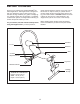
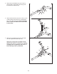
9. Attach the Leg Lever (46) to the Frame (1) with a
Short Bolt Set (24) and an M8 Washer (33). Next,
insert the Leg Lever Lock (38) into the indicated
hole in the Leg Lever and the Frame. Do not
overtighten the Short Bolt Set; the Leg Lever
must be able to pivot easily.
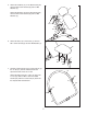
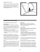
10. Insert the Pad Tube (13) into the indicated hole in
the Frame (1). Slide two Foam Pads (12) onto the
Pad
T
ube. Press two Medium Inner Caps (1
1)
into the Pad Tube.
Slide two Foam Pads (12) onto the Leg Lever
(46). Press two Medium Inner Caps (11) into the
Leg Lever.
1
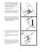
1. Make sure that all parts are properly tightened.
The use of the remaining parts will be explained
in ADJUSTMENTS, beginning on the next page.
If the weight bench is not level on your floor,
rotate one or both of the Levelling Endcaps (4)
until the weight bench is level.
8
9
10
44
24
24
1
46
38
33
Hole
Hole
13
12
12
46
11
12
12
11
11
11
4
4
1
18
19
40
27
28
20