
User`s manual

8
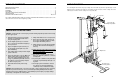
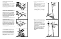
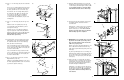
12. Press two 1 3/4” Inner Caps (44) into each of the
Arms (46).
Apply lubricant to the lower axles on the Arm
Frame (52). Slide an Arm (46) onto one of the
axles. Hold two 1” Retainers (54) and a 1” Round
Cover Cap (55) against the lower end of the axle.
The teeth on the Retainers must bend toward
the Round Cover Cap (see inset drawing). Tap
the Retainers and Round Cover Cap onto the axle.
Attach the other Arm (46) to the Arm Frame (52) in
the same manner.
Insert the two 4 1/2” “L” Pins (60) down through the
indicated holes in the Arm Frame (52) and the
Arms (46).
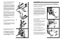
13. Wet both Arms (46) with soapy water. Slide a 7 3/4”
Pad (45) onto each Arm.
Press a 1” Round Inner Cap (49) into the indicated
end of a 7” Handle (47). Wet the other end of the
Handle with soapy water and slide a Handgrip (12)
onto it. Insert the Handle into one of the Arms (46).
Attach the Handle with a 5/16” x 2 1/4” Bolt (33),
two 5/16” Flat Washers (8), a 1/2” x 3/8” Spacer
(51) and a 5/16” Nylon Locknut (3).
Attach a 7” Handle (47) to the other Arm (46) in the
same manner.
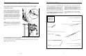
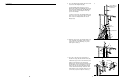
14. Attach a Large “U” Bracket (56) to one of the Arms
(46) with a 3/8” x 2 3/4” Bolt (70), 3/8” Flat Washer
(9), and 3/8” Nylon Locknut (21). Be sure that the
Cable Trap (59) is on the side shown.
Attach a Large “U” Bracket (56) to the other Arm
(46) in the same manner.
14
21
56
70
70
21
59
59
56
9
9
46
46
13
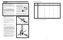
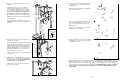
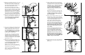
30. Attach a VKR Armrest (99) to the Right VKR Arm
(101) with two 1/4” x 2” Screws (102) and 1/4”
Flat Washers (10).
Attach a VKR Armrest (99) to the Left VKR Arm
(100) in the same manner.
31. Insert a 7” Handle (47) into the Right VKR Arm
(101). Attach the Handle with a 5/16” x 2” Bolt
(61), two 5/16” Flat Washers (8), and a 5/16”
Nylon Locknut (3).
Attach the other 7” Handle (47) to the Left VKR
Arm (100) in the same manner.
32. Attach the VKR Backrest (98) to the Rear Upright
(82) with two 1/4” x 2 1/2” Screws (43) and two
1/4” Flat Washers (10).
30
31
32
99
101
100
10
102
99
61
8
8
3
101
100
47
47
98
82
10
43
12
55
44
47
12
45
8
49
8
46
46
3
46
46
44
52—Lubricate
54
60
44
44
42
54
13
55
52
54
47
33
45
51
33. Make sure that all parts are properly tightened. The use of all remaining parts will be explained in ADJUST-
MENT, beginning on page 15 of this manual. Before using the weight system, pull each cable a few times to
make sure that the cables move smoothly over the pulleys. If one of the cables does not move smoothly,
locate and correct the problem before using the weight system. IMPORTANT: If the cables are not proper-
ly routed, they may be damaged when heavy weight is used. See the CABLE DIAGRAM on page 19
of this manual.