
User`s manual

3
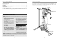
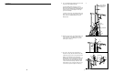
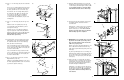
BEFORE YOU BEGIN
ASSEMBLED
DIMENSIONS:
Height: 75 1/2 in.
Width: 55 3/4 in.
Length: 72 in.
Foot Plate
Low Pulley Station
High Pulley Station
Lat Bar
Leg Lever
Arms
Stepper
Weight Stack
Backrest
Resistance Cylinders
VKR Arms
Weight Pin
18
Thank you for selecting the versatile WEIDER
®
VIPER
2000. The VIPER 2000 offers a selection of weight
stations designed to develop every major muscle
group of the body. Whether your goal is to tone your
body, build dramatic muscle size and strength, or
improve your cardiovascular system, the VIPER 2000
will help you to achieve the specific results you want.
For your benefit, read this manual carefully before
using the WEIDER
®
VIPER 2000. If you have addi-
tional questions, please call our Customer Service
Department. To help us assist you, please note the
product model number and serial number before call-
ing. The model number is WESY60400. The serial
number can be found on a decal attached to the
VIPER 2000 (see the front cover of this user's manual).
Before reading further, please review the drawing
below and familiarise yourself with the parts that are
labelled.
TROUBLE-SHOOTING AND MAINTENANCE
Inspect and tighten all parts each time you use the weight system. Replace any worn parts immediately. The
weight system can be cleaned using a damp cloth and mild non-abrasive detergent. Do not use solvents.
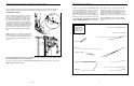
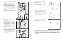
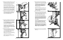
TIGHTENING THE CABLES
Woven cable, the type of cable used on the weight
system, can stretch slightly when it is first used. If
there is slack in the cables before resistance is felt,
the cables should be tightened. Locate the adjust-
ment sleeve and adjustment screw near the lower
end of the Short Cable (23). Loosen the adjustment
screw. Pull the end of the Short Cable until there is no
slack. Slide the adjustment sleeve and the ball against
the indicated 3 1/2” Pulley (15). Retighten the adjust-
ment screw. Make sure that the cables are not too
tight, or the top weight will be lifted off the weight
stack.
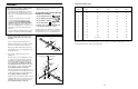
Additional slack can be removed by locating the indi-
cated 5/16” Nylon Locknut (3) near the upper end of
the Front Upright (42). To tighten the cables, hold the
5/16” x 3 1/4” Bolt (35) and turn the Nylon Locknut
clockwise.
Note: Inspect all cables before each use. If a cable tends to slip off the pulleys often, the cable may have
become twisted. Remove the cable and re-install it.
If the cables need to be replaced, see ORDERING REPLACEMENT PARTS on the back cover of this manual.
Replace all cables every two years.
23
15
15
Adjustment
Screw
Adjustment
Sleeve
Ball
23
35
3
42