
User`s manual

19
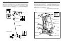
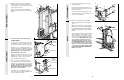
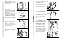
40. Locate and open the parts bag labelled
“SEAT ASSEMBLY.”
Insert a 1/4” x 2 1/2” Carriage Bolt (92)
through the centre hole in a Seat Plate (37).
Attach the Seat Plate to the Rear Backrest
(85) with two 1/4” x 1/2” Screws (18).
Insert the 1/4” x 2 1/2” Carriage Bolt (92)
through the indicated hole in the Leg Press
Upright (56). Tighten a 1/4” Nylon Locknut (2)
with a 1/4” Flat Washer (10) onto the Carriage
Bolt. Attach the top of the Rear Backrest (85)
to the Leg Press Upright with a 1/4” x 2 1/2”
Screw (43) and a 1/4” Flat Washer (10).
41. Attach one end of a Seat (13) to the Rear
Seat Frame (100) with two 1/4” x 1/2” Screws
(18). Attach the other end of the Seat to the
Rear Seat Frame with a 1/4” Flat Washer (10)
and a 1/4” x 2 1/2” Screw (43).
42. Attach the Assist Seat (104) and the Angle
Bracket (110) to the Assist Arm (105) with four
1/4” Flat Washers (10) and four 1/4” x 2 1/2”
Screws (43).
SEAT ASSEMBLY
10
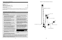
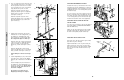
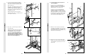
15. See the inset drawing. Attach the Military
Press Arm (84) to the Pivot Arm (101) with
two 5/16” x 2 1/4” Bolts (33) and two 5/16”
Nylon Locknuts (3).
Press two 1 1/2” Square Inner Caps (32) into
the Military Press Arm (84). Press two 1”
Round Inner Caps (49) into the Military Press
Arm. Slide two 5” Plastic Handgrips (83) onto
the Military Press Arm.
Attach the Pivot Arm (101) to the Assist
Upright (74) with a 3/8” x 3 1/4” Bolt (67) and
a 3/8” Nylon Locknut (21).
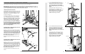
16. Press two 1” x 2” Inner Caps (107) into the
Assist Arm (105).
Attach the Assist Arm (105) to the Leg Press
Upright (56) with a 3/8” x 6” Bolt (106), two
3/8” Flat Washers (9), and a 3/8” Nylon
Locknut (21). See the inset drawing. The
Assist Arm must be attached to the lowest
hole in the Leg Press Upright (56). The
Assist Arm must also be below the welded
bracket on the Assist Upright (74).
15
49
32
83
84
84
101
101
21
67
5674
33
3
ARM ASSEMBLY
32
42
40
4116
107
106
105
105
Bracket
56
56
21
9
9
85
2
10
18
92
56
37
43
18
18
13
10
43
10
10
43
104
105
100
110
74
74