
User`s manual

12
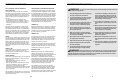
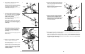
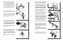
23. Have a second person lift the Top Weight (not
shown) to create slack in the Long Cable (80).
Slide one end of the Cable through the Swivel
Arm (22). Make sure the Cable is on the indi-
cated side of the rod in the Swivel Arm.
Wrap the Long Cable (80) around a Large Pulley
(28). Attach the Pulley and a Arm Pulley Cover
(87) to the Swivel Arm (22) with an M10 x 45mm
Bolt (2) and an M10 Nylon Locknut (76).
25. Wrap the Bench Cable (32) under a Large Pulley
(28). Attach the Pulley and a pair of Pulley
Covers (29) inside the hole in the Front Leg (6)
with an M10 x 65mm Bolt (79), two 8mm Spacers
(52), two M10 Washers (75), and an M10 Nylon
Locknut (76). Make sure that the small tabs on
the Pulley Covers are on the bottom.
Slide the two free ends of the Bench Cable (32)
onto the eyebolt welded to the bottom of the
Bench Frame (5).
26. Locate the two Short Cables (33). Wrap a Short
Cable over a Large Pulley (28). Attach the Pulley
and a pair of Pulley Covers (29) to a Pulley
Housing (21) with an M10 x 50mm Bolt (71) and
an M10 Nylon Locknut (76). Make sure that the
small tabs on the Pulley Covers are on the
bottom.
Repeat this step with the other Short Cable
(33).
24. Locate the Bench Cable (32). It has three ends,
two that are the same length, and a third that is
shorter.
Route the short end of the Bench Cable (32)
through the hole in the Front Leg (6), and attach it
inside the slot in the Leg Lever (7) with an M10 x
62mm Bolt (63), two M10 Washers (75), and an
M10 Nylon Locknut (76).
23
24
25
26
9
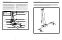
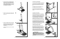
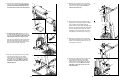
12. Lubricate two Small Wheels (47) with grease. Slide
a Steel Tube (57) into a 32mm Spacer (46). Orient
the Wheels as shown in the inset drawing, and
slide them onto the ends of the Steel Tube.
Attach the wheel assembly to the indicated set of
holes in the Seat Carriage (12) with an M8 x
84mm Bolt (60) and an M8 Nylon Locknut (65). Do
not overtighten the Locknut; the Small Wheels
(47) must pivot freely. Repeat with another
wheel assembly and an M8 x 82mm Bolt (95).
Orient the Seat (13) and the Seat Carriage (12)
as shown. Attach the Seat to the Seat Carriage
with four M6 x 16mm Screws (82).
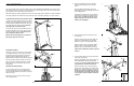
13. Lubricate two Small Wheels (47) with grease. Slide
a Steel Tube (57) into a 32mm Spacer (46). Orient
the Wheels as shown in the inset drawing, and
slide them onto the ends of the Steel Tube.
Set the Seat Carriage (12) on the Bench Frame
(5). Have one person press the Seat (13) against
the Bench Frame. Press the wheel assembly tight
against the bottom of the Bench Frame and attach
it to the lowest set of holes in the Seat Carriage
with an M8 x 84mm Bolt (60) and an M8 Nylon
Locknut (65). Do not overtighten the Locknut;
the Small Wheels (47) must pivot freely.
Slide the Seat Pin (45) through the Seat Carriage
(12) and an adjustment hole in the Bench Frame
(5).
15. Orient the Backrest (14) as shown. Attach the
Backrest to the Backrest Frame (15) with four M6
x 38mm Screws (58) and four M6 Washers (77).
14. Press two 25mm Square Inner Caps (54) into the
indicated ends of the Backrest Frame (15). Press
the Backrest Cap (16) onto the other end of the
Backrest Frame. Attach a Plastic Foot (53) to the
Backrest Frame with an M4 Washer (92), and an
M4 x 25mm Screw (56).
Attach a Guard Plate (17) to the inside of the
Backrest Frame (15) with two M4 x 10mm Screws
(96). Attach the other Guard Plate in the same
manner.
12
13
14
15
13
60
95
Wheel
Assembly
Wheel
Assembly
12
65
65
82
82
80
28
2
76
22
87
Rod
76
75
75
32
6
63
7
29
29
75
75
76
79
52
52
28
32
5
6
Eyebolt
Small
Tab
Small
Tab
76
71
21
28
33
29
29
45
60
65
47
46
57
47
Adjustment
Hole
12
13
5
16
53
56
92
15
54
17
96
17
15
77
77
58
58
14
Small
Side
Large Side
47
47
57
46
Small
Side
Large Side
47
47
57
46