
User`s manual

13
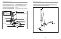
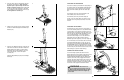
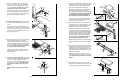
27. Press two 19mm Round Inner Caps (78) into the
ends of a Pad Tube (89). Slide the Tube into the
hole in the Leg Lever (7). Slide two Foam Pads
(26) onto the Pad Tube.
Attach the other Pad Tube (89) to the Front
Leg (6) in the same manner.
28. Attach the “FLEX 8960” exercise decal to the
Upright (3) and the Top Upright (4). The decal
should be centred on the Upright and Top
Upright, and the top of the decal should be six
inches below the Top Frame (9). Be careful
not to wrinkle the decal.
29.
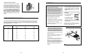
Make sure that all parts have been properly tightened. The use of the remaining parts will be explained in
ADJUSTMENTS, beginning on the following page.
Before using the weight system, pull the long cable a few times to be sure that it moves smoothly over the
pulleys. If the cable does not move smoothly, find and correct the problem. IMPORTANT: If the cables are
not properly installed, they may be damaged when heavy weight is used. See the CABLE DIAGRAM
on page 17 for proper cable routing.
27
28
8
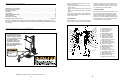
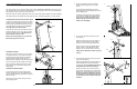
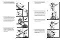
8. Press two 40mm x 50mm Inner Caps (41) into
the ends of the Cross Frame (11).
Orient the Cross Frame (11) as shown, with the
welded tube near the top. Attach the Cross Frame
to the Upright (3) with two M10 x 105mm
Carriage Bolts (73), two M10 Washers (75), and
two M10 Nylon Locknuts (76).
10. Lubricate the M10 x 80mm Bolt (66) with grease.
Attach the Bench Frame (5) to the Upright (3)
with the Bolt and an M10 Nylon Locknut (76) at
the indicated hole. Do not overtighten the
Locknut; the Bench Frame must be able to
pivot easily.
Tighten the Knob (30) into the Upright (3) and the
Bench Frame (5).
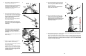
11. Attach the Leg Lever Bumper (55) to the Front
Leg (6) with the M4 x 25mm Screw (56).
Press two 45mm Square Inner Caps (42) into the
ends of the Leg Lever (7).
Lubricate an M10 x 70mm Bolt (64) with grease.
Attach the Leg Lever (7) to the Front Leg (6) with
the Bolt and an M10 Nylon Locknut (76). Do not
overtighten the Locknut; the Leg Lever must
be able to pivot easily.
9. Press a 40mm x 50mm Inner Cap (41) into the
top of the Front Leg (6). Press the Front Leg Foot
(27) onto the bottom of the Front Leg. Note that
the front of the Front Leg Foot is taller and
slants more than the back.
Press a 40mm x 50mm Inner Cap (41) into the
end of the Bench Frame (5).
Attach the Bench Frame (5) to the Front Leg (6)
with two M10 x 57mm Carriage Bolts (61) and
two M10 Nylon Locknuts (76). Do not tighten the
Locknuts yet.
8
9
10
11
41
3
73
41
Welded
Tube
11
76
75
75
78
26
7
6
89
26
89
4
9
6”
3
78
5
41
76
41
27
61
6
Back
76
30
66
Lubricate
Hole
5
3
64
76
6
7
42
56
55
42
Lubricate