
User`s manual
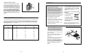

This section explains how to adjust the weight system. See the EXERCISE GUIDELINES on page 18 for impor-
tant information about how to get the most benefit from your exercise program. Also, refer to the accompanying
exercise guide to see the correct form for each exercise.
Make sure all parts are properly tightened each time you use the weight system. Replace worn parts immediately.
The weight system can be cleaned with a damp cloth and a mild, non-abrasive detergent. Do not use solvents.
14
Ball
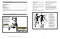
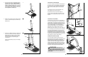
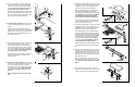
ATTACHING THE HIGH PULLEYS AND LEG LEVER
To attach a high pulley, slide the eyebolt on the Pulley
Housing (21) onto the Eyebolt (34). Attach the end of
the Short Cable (33) without the ball to the end of the
Long Cable (80) with a Cable Clip (51). Attach the
other high pulley in the same manner.
To use the Leg Lever (not shown), attach the ends of
the Bench Cable (32) to the ends of the Long Cable
(80) with two Cable Clips (51). Note that only one
side of the Bench Cable is shown.
Remove the Pulley Housings (21), or detach the
Bench Cable (32), when not in use.
33
21
51
80
32
34
ADJUSTMENTS
7
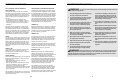
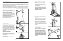
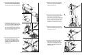
6. Press a 45mm Square Inner Cap (42) into the
Top Frame (9).
Attach the Top Frame (9) to the Top Upright (4)
with an M10 x 65mm Bolt (79), an M10 Split
Washer (43), and an M10 Large Washer (90).
Attach the Top Frame (9) to the Weight Guides
(8) with an M10 x 155mm Bolt (85), two M10
Washers (75), and an M10 Nylon Locknut (76).
Tighten the two M10 Nylon Locknuts (76) used
in step 2.
7. Press two 38mm Round Inner Caps (40) into the
ends of the Crossbar (10).
Attach the two Eyebolts (34) to the Crossbar (10)
with two M8 Washers (59) and two M8 Nylon
Locknuts (65). Do not overtighten the Locknuts;
the Eyebolts must be able to rotate freely.
Attach the Crossbar (10) to the Top Frame (9)
with two M10 x 56mm Bolts (70), two M10 Small
Washers (91), and two M10 Nylon Locknuts (76).
Be sure the Crossbar is attached as shown in
the inset drawing. If the ends point away from
the Top Frame, turn the Crossbar around and
reattach it.
7
6
8
85
90
43
79
4
10
91
70
76
9
65
59
40
40
59
65
34
34
42
9
75
75
76
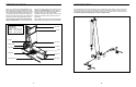
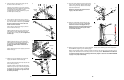
ADJUSTING THE SEAT
The Seat (13) can be secured to any of four positions
on the Bench Frame (5). To move the Seat, remove
the Seat Pin (45) and slide the Seat to the desired
position. Engage the Seat Carriage (12) and an
adjustment hole in the Bench Frame with the Seat Pin.
For some exercises the Seat Carriage (12) must be
able to roll freely on the Bench Frame (5). To allow
this to happen, remove the Seat Pin (45) from the
Seat Carriage.
LOCKING THE WEIGHT STACK
To prevent unapproved use of the weight system,
insert the Locking Pin (37) into the indicated hole in
one of the Weight Guides (8). Secure the Locking Pin
with the Lock (74).
Remove the Lock (74) and the Locking Pin (37) to
use the weight system.
13
45
12
5
74
8
37
5. Slide the nine Weights (35) onto the Weight
Guides (8) with the pin grooves on the side
shown.
Press the Weight Tube Bumper (18) into the
Weight Tube (44). Insert the Weight Tube into the
stack of Weights (35).
Lubricate the indicated holes in the Top Weight
(86) with grease. Slide the Top Weight onto the
Weight Guides (8). Make sure the pin on the
Weight Tube (44) rests in the groove on the
bottom of the Top Weight.
5
86
8
44
Pin
Lubricate
Pin
Groove
18
35
10
9