
User`s manual

15
14
14
12
Rod
Slot
4
5
13
6
30
Eyebolt
32
12
6
3
5
3
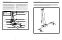
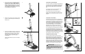
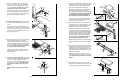
ADJUSTING THE BACKREST
The Backrest (14) can be used in a level position or
one of three inclined positions. To use the Backrest in
a level position, secure the Seat Carriage (12) to the
adjustment hole in the Bench Frame (5) closest to the
Front Leg (6) (see ADJUSTING THE SEAT on page
14). To use the Backrest in an inclined position,
secure the Seat Carriage to one of the other three
adjustment holes in the Bench Frame. Rest the
Backrest against the Upright (3) or the Top Upright (4).
For row exercises, the seat must be able to roll freely
(see ADJUSTING THE SEAT on page 14), the leg
press strap must be attached (see ATTACHING THE
ACCESSORIES, above), and the Backrest (14) must
be removed. To remove the Backrest, hold it vertically
over the Seat (13) and lift the rod out of the slot in the
Seat Carriage (12) (see the inset drawing).
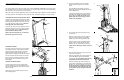
STORING THE WEIGHT SYSTEM
To store the weight system, slide the ends of the
Bench Cable (32) onto the eyebolt on the bottom of the
Bench Frame (5). Then remove the backrest (see
ADJUSTING THE BACKREST above). Make sure the
Seat Pin (not shown) is fully engaged into the Seat
Carriage (12) and the Bench Frame. Next, remove the
Knob (30) from the Upright (3). Lift the Front Leg (6)
toward the Crossbar (not shown), and tighten the Knob
into the side of the Upright and the Bench Frame.
6
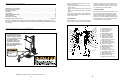
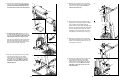
4. Orient the two Weight Guides (8) so that the indi-
cated holes are closer to the bottom. Attach the
Weight Guides to the Base (1) with two M10 x
62mm Bolts (63), four M10 Washers (75), four
10mm Spacers (94), and two M10 Nylon
Locknuts (76).
Slide two Weight Bumpers (39) onto the Weight
Guides (8).
2. Insert two M10 x 62mm Carriage Bolts (83) into
the bottom of the Base (1). (Note: It may be
helpful to place a peice of tape over the bolt
heads to hold them in place.) Set the Base flat
on the floor. Attach the Upright (3) to the Base
with the Bolts and two M10 Nylon Locknuts (76).
Do not tighten the Locknuts yet.
4
2
8
Holes
39
75
94
76
76
39
63
75
1
3
76
1
83
94
88
88
19
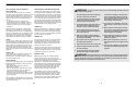
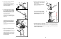
ATTACHING THE ACCESSORIES
To use the Lat Bar (19), first attach the high pulleys to
the weight system (see ATTACHING THE HIGH PUL-
LEYS on page 14). Then attach the Lat Harnesses
(88) to the Short Cables (33) with two Cable Clips
(51).
The Handles (not shown) can be attached to the
Short Cables (33) in the same manner.
The Handles (not shown), the Ankle Strap (not
shown), or the Leg Press Strap (not shown) can be
attached to the Long Cable (not shown) in a similar
manner.
33
33
51
51
3. Attach the Top Upright (4) to the Upright (3) with
four M10 x 20mm Bolts (68) and four M10 Split
Washers (43).
3
4
3
68
43
43
WARNING: Be careful not to
pinch your fingers when raising the front Leg
(6). Make sure the storage Knob (30) is in place
and fully tightened each time the weight sys-
tem is used.
75