
User's Manual


9
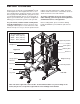
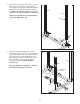
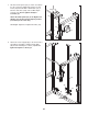
4. Identify the Left Safety Spotter (51), which has a
round opening on the side shown. Loosen the two
A
djustment Knobs (22) on the Left Safety Spotter
by turning them counterclockwise. Next, pull both
A
djustment Knobs at the same time and slide the
Left Safety Spotter (51) onto the Left Uprights
(43, 44). Then, engage the Adjustment Knobs into
a set of adjustment holes in the Uprights. Do not
tighten the Adjustment Knobs yet.
Repeat this step with the Right Safety Spotter
(not shown) and the Right Uprights (not
shown).
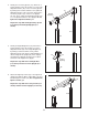
5. Identify the Right Weight Rest (52), which has a
round opening on the side shown. Loosen the
Adjustment Knob (22) on the Right Weight Rest
by turning it counterclockwise. Next, pull the
Adjustment Knob and slide the Right Weight Rest
onto the Right Front Upright (30). Then, engage
and tighten the Adjustment Knob into an adjust-
ment hole in the Right Front Upright.
Repeat this step with the Left Weight Rest
(not shown) and the Left Front Upright (not
shown).
6. Attach the Right Top Frame (47) to the right Rear
Upright (43) with two M10 x 78mm Bolts (32) and
two M10 Nylon Locknuts (34). Do not tighten the
Nylon Locknuts yet.
Repeat this step with the Left Top Frame (not
shown) and the left Rear Upright (not shown).
4
51
22
Round
Opening
Round
Opening
22
30
44
43
22
5
6
52
47
32
43
34