
User`s manual

16
ADJUSTMENT
The instructions below describe how each part of the weight system can be adjusted. IMPORTANT: When
attaching the lat bar or handle, make sure that the accessories are in the correct starting position for the
exercise to be performed. If there is any slack in the cable or chain as an exercise is performed, the
effectiveness of the exercise will be reduced.
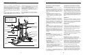
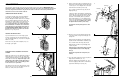
CHANGING THE WEIGHT SETTING
To change the weight setting, insert the Weight Pin
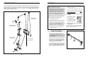
(20) under one of the Weights (16). Make sure to
insert the Weight Pin until the bent end of the Weight
Pin is touching the Weights, and turn the bent end
downward. The weight setting can be changed from
12.5 pounds to 125 pounds, in increments of 12.5
pounds. Important: Due to the cables and pulleys,
the actual amount of resistance at each exercise
station will vary from the weight setting. Refer to
the WEIGHT RESISTANCE CHART on page 18 to
find the actual amount of resistance at each sta-
tion. Note: 1 kg = 2,2 pounds.
LOCKING THE WEIGHT STACK
To prevent unauthorised use of the weight system,
insert the Locking Bar (21) into the indicated hole in
one of the Weight Guides (5). Secure the Locking Bar
with the Lock (22).
Remove the Lock (22) and Locking Bar (21) to use
the weight system again.
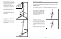
ATTACHING THE ACCESSORIES TO A PULLEY
STATION
Attach the Lat Bar (101) to the High Cable (57) with a
Cable Clip (68). For some exercises, the Chain (99)
should be attached between the Lat Bar and the High
Cable with two Cable Clips. Adjust the length of the
Chain between the Lat Bar and the High Cable so
that the Lat Bar is in the correct starting position
for the exercise to be performed.
The Handle (not shown) can be attached in the same
manner. The accessories can be attached to the Low
Cable (not shown) in the same manner.
20
16
5
22
21
68
68
101
99
57
9
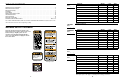
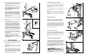
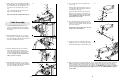
9. Attach a Cable Pivot (58) to the Right Fly Arm (9)
with an M10 x 50mm Bolt (85) and an M10 Nylon
Locknut (72). Do not overtighten the Locknut; the
Cable Pivot must be able to pivot easily.
Press a 40mm x 50mm Inner Cap (23) into the
Right Fly Arm (9).
Lubricate an M10 x 83mm Button Head Bolt (86)
and the flat sides of two Plastic Washers (59) with
grease. Attach the Right Fly Arm (9) to the indi-
cated side of the Butterfly Frame (11) with the
Bolt, two M10 Washers (71), two Butterfly Caps
(60), the two Plastic Washers, and an M10 Nylon
Locknut (72). Do not overtighten the Locknut;
the Fly Arm must be able to pivot easily.
Assemble the Left Fly Arm (10) in the same
manner.
10. Wet the lower end of the Right Fly Arm (9) with
soapy water. Slide a Large Foam Pad (65) onto
the Fly Arm.
Attach an Arm Handle (24) to the Right Fly Arm
(9) with two M8 x 20mm Button Head Bolts (84).
Press a 25mm Dome Inner Cap (25) into the
Right Fly Arm (9). Slide a Long Handgrip (102)
onto the Fly Arm.
Slide the Large Foam Pad (65) down so that it
is aligned with the bottom of the Right Fly
Arm (9).
Repeat this step with the Left Fly Arm (not
shown).
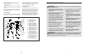
11. Press two 38mm Square Inner Caps (29) into the
Right and Left VKR Arms (12, 13).
Attach the Right and Left VKR Arms (12, 13) to
the Rear Upright (3) with two M10 x 72mm Bolts
(89) and two M10 Nylon Locknuts (72).
11
29
29
13
12
72
3
89
89
9
9
65
84
84
102
Lubricate
Lubricate
Lubricate
72
23
11
10
85
58
86
71
71
60
60
72
59
9
59
10
24
25