
User`s manual
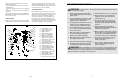
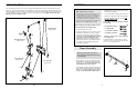
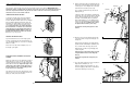

CONVERTING THE BUTTERFLY ARMS
To use the Fly Arms (9, 10) as butterfly arms, insert
the “L”-pins (100) into the butterfly holes in the Front
Upright (4) and the tab on the back of the Butterfly
Frame (11).
To use the Fly Arms (9, 10) as press arms, insert the
“L”-pins (100) into the press holes in the Butterfly
Frame (11).
Make sure that the “L”-pins (100) are fully inserted
into the same set of holes before performing any
exercises.
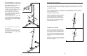
ATTACHING THE SEAT
Set the Seat Frame (7) on the pin on the Front
Upright (4). Secure the Seat Frame with an M8 x
67mm Carriage Bolt (82) and the M8 Knob (106).
For some exercises, the Seat (7) must be removed.
First, make sure that the chain is not attached to the
leg lever (see ATTACHING THE LEG LEVER, below).
Next, remove the M8 Knob (106) and M8 x 67mm
Carriage Bolt (82) from the Seat Frame. Lift the Seat
Frame off the Front Upright (4).
ATTACHING THE LEG LEVER
To use the Leg Lever (8), first attach the seat to the
weight system (see ATTACHING THE SEAT, above).
Next attach the Low Cable (56) to the M10 x 63mm
Eyebolt (97) with the Chain (99) and two Cable Clips
(68).
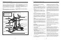
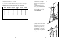
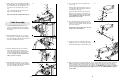
CHANGING THE STEPPING RESISTANCE
To change the stepping resistance, lift the Right and
Left Pedals (14, 15) off the hooks at the lower ends of
the Resistance Cylinders (37). Move the hooks to dif-
ferent slots under the Pedals. Make sure that the
hooks are fully inserted into the slots in the same
position under both Pedals. The farther the hooks
are moved from the Rear Upright (3), the greater the
resistance will be.
100
11
4
100
Butterfly
Press
97
8
56
68
68
99
106
82
7
4
Pin
37
14
15
17
WARNING: The Resistance
Cylinders (37) become very hot during use.
Allow the Resistance Cylinders to cool before
touching them.
8
6
7
8
Pedal
Axle
Cylinder
Axle
Hook
Warning Decals
Slotted
Brackets
40
39
38
74
75
75
35
14
15
36
98
3
30
14
37
37
3
72
11
74
83
100
103
6
Lubricate
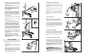
6. Press two 38mm Square Bushings (35) into the
Right Pedal (14); Attach a Pedal Cover (36) to the
Pedal with two M4 x 16mm Self-tapping Screws
(74) and two M4 Washers (75).
Lubricate the pedal axles on the Rear Upright (3).
Slide the Right Pedal (14) onto the pedal axle.
Make sure that the Pedal is on the correct
side; the slotted brackets must be on the
inside of the Pedal.
Hold a 25mm Retainer (98) and 25mm Round
Outer Cap (30) against the right pedal axle. The
teeth on the Retainer must bend toward the
Round Cover Cap (see the inset drawing in
step 7). Tap the Retainer and Round Outer Cap
onto the pedal axle.
Attach the Left Pedal (15) in the same manner.
7. Lubricate the cylinder axles on the Rear Upright
(3) with grease.
Slide a 16mm Round Bushing (40) and a
Resistance Cylinder (37) onto the right cylinder
axle. Make sure that the Bushing, Cylinder,
and warning decal are oriented as shown.
Hold a 16mm Retainer (39) and a 16mm Round
Outer Cap (38) against the right cylinder axle.
The teeth on the Retainer must bend toward
the Outer Cap (see the inset drawing). Tap the
Retainer and Outer Cap onto the cylinder axle.
Raise the Right Pedal (14) and rest it on the hook
at the lower end of the Resistance Cylinder (37).
The hook must be in one of the slots under
the right Pedal.
Repeat this step with the other Resistance
Cylinder (37) on the left side of the Rear
Upright (3). Tighten the Nylon Locknuts (72, 73)
used in steps 2–7.
8. Press a 50mm x 70mm Inner Cap (103) into the
Butterfly Frame (11).
Attach the tethers on the two “L”-pins (100) to the
Butterfly Frame (11) with an M4 x 16mm Self-tap-
ping Screw (74).
Lubricate an M10 x 80mm Bolt (83) with grease.
Attach the Butterfly Frame (11) to the Top Frame
(6) with the Bolt and an M10 Nylon Locknut (72).
Do not overtighten the Locknut; the Butterfly
Arm must be able to pivot easily.
30, 38
Axle
39, 98
Arm Assembly