
User`s manual

19
TROUBLESHOOTING
Make sure all parts are properly tightened each time the weight system is used. Replace any worn parts immedi-
ately. The weight system can be cleaned using a damp cloth and mild non-abrasive detergent. Do not use solvents.
TIGHTENING THE CABLES
Woven cable, the type of cable used on the weight system, can stretch slightly when it is first used. If there is
slack in the cables before resistance is felt, the cables should be tightened. Slack can be removed from the
cables in several different ways.
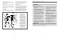
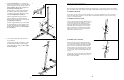
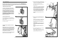
TIGHTENING THE PULLEY PLATES
Slack can be removed by moving a 90mm Pulley (not
shown) and the Pulley Covers (49) to a set of holes
closer to the centre of the two Pulley Plates (50).
Remove the M10 Nylon Locknut (72) and the M10 x
53mm Bolt (88) from the Pulley Covers, the Pulley,
and the Pulley Plates. Re-attach the Pulley and the
Pulley Covers to the new set of holes in the Pulley
Plates with the Bolt and Locknut.
TIGHTENING THE “U”-BRACKET
Slack can be removed by moving the 90mm Pulley
(not shown) and the Pulley Covers (49) to the upper
set of holes in the “U”-bracket (53). Remove the M10
Nylon Locknut (72) and the M10 x 53mm Bolt (88)
from the Pulley Covers, the Pulley, and the “U”-brack-
et. Re-attach the Pulley and the Pulley Covers to the
new set of holes in the “U”-bracket with the Bolt and
Locknut.
Slack can also be removed from the Short Cable (94)
by tightening the M8 Nylon Locknut (73) a couple of
turns onto the Short Cable.
50
49
72
88
72
73
53
94
88
49
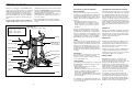
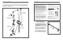
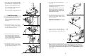
2. See the inset drawing. Press a 50mm Square
Inner Cap (31) into the Base (1). Insert two M10 x
65mm Carriage Bolts (81) up through the Base. It
may be helpful to place a piece of tape over
the bolt head to hold it in place.
Attach the Base (1) and the Rear Upright (3) to
the Stabiliser with the indicated M8 x 67mm
Carriage Bolts (82) and two M8 Nylon Locknuts
(73). Do not tighten the Locknuts yet.
Attach the Support Bracket (33) to the M10 x
67mm Carriage Bolt (107) with an M10 Star
Washer (92) and an M10 Nylon Locknut (72). Do
not tighten the Locknuts yet.
Orient the Support Bracket (33) as shown. Attach
the Support Bracket to the Rear Upright (3) with
an M10 x 72mm Bolt (89), an M10 Washer (71),
and an M10 Nylon Locknut (72). Do not tighten
the Locknuts yet.
2
3
3
81
71
89
73
73
72
33
92
1
31
1
2
82
107
29
72
81
72
4
6
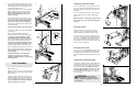
3. Press a 38mm Square Inner Cap (29) into the
Front Upright (4).
Attach the Front Upright (4) to the Base (1) with
the indicated M10 x 65mm Carriage Bolts (81)
and two M10 Nylon Locknuts (72). Do not tight-
en the Locknuts yet.
Hole
Slot