
User`s manual


24
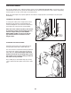
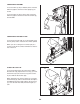
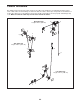
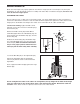
The drawings below shows the proper routing of the cables. The numbers in each drawing show the proper
r
oute of that cable. Use the drawings to make sure that the cables, cable traps, and guards are assembled cor-
rectly. If the cables are not assembled correctly, the weight system will not function properly and damage may
occur. Make sure that the cable traps do not touch or bind the cables.
1
2
4
2
3
4
5
5
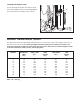
Arm Cable (54)
Length: 101 in. (257 cm)
High Cable (55)
Length: 126 in. (320 cm)
Low Cable (53)
Length: 122 in. (310 cm)
3
1
6
1
2
3
4
5
6
CABLE DIAGRAM