
User`s manual

9
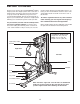
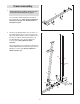
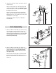
6. Orient the Top Frame (4) with the welded support
on the bottom.
A
ttach the Top Frame (4) to the Upright (3) with
two M8 x 65mm Bolts (68), two M8 Washers (59),
a
nd two M8 Nylon Locknuts (58). Do not tighten
the Nylon Locknuts yet.
Attach the Top Frame (4) between the Weight
Guides (21) with an M10 x 155mm Bolt (74), two
M10 Washers (57), two 19mm Spacers (76), and
an M10 Nylon Locknut (56).
See steps 2–4, and 6. Tighten the M8 Nylon
Locknuts (58).
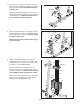
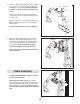
7. Grease an M10 x 77mm Bolt (79). Orient the Leg
Lever (8) with the welded support on the side
shown. Attach the Leg Lever to the Front Leg (7)
with the Bolt and an M10 Nylon Locknut (56). Do
not overtighten the Nylon Locknut; the Leg
Lever must pivot easily.
8. Grease an M10 x 77mm Bolt (79). Attach the
Pivot Frame (5) to the Top Frame (4) with the Bolt
and an M10 Nylon Locknut (56). Do not over-
tighten the Nylon Locknut; the Pivot Frame
must pivot easily.
Attach the two Arm Pins (40) to the Pivot Frame
(5) with two M4 x 20mm Self-tapping Screws
(69). Insert the Arm Pins into the two holes in the
Upright (3).
Arm Assembly
Grease
Holes
5
56
79
69
69
3
40
40
4
8
56
79
Grease
Welded
Support
7
8
7
4
Welded
Support
3
58
56
74
21
21
5
9
57
5
7
59
76
76
68
58
6