Model No. WESY1938.0 Serial No. Write the serial number in the space above for future reference. USERʼS MANUAL Serial Number Decal (under seat) QUESTIONS? As a manufacturer, we are committed to providing complete customer satisfaction. If you have questions, or if parts are missing, PLEASE DO NOT CONTACT THE STORE; please contact Customer Care. IMPORTANT: You must note the product model number and serial number (see the drawing above) before contacting us: 1-877-992-5999 CALL TOLL-FREE: Mon.–Fri.
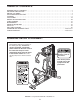
TABLE OF CONTENTS WARNING DECAL PLACEMENT . . . . . . . . . . . . . . . . . . . . . . . . . . . . . . . . . . . . . . . . . . . . . . . . . . . . . . . . . . . . . 2 IMPORTANT PRECAUTIONS . . . . . . . . . . . . . . . . . . . . . . . . . . . . . . . . . . . . . . . . . . . . . . . . . . . . . . . . . . . . . . . . 3 BEFORE YOU BEGIN . . . . . . . . . . . . . . . . . . . . . . . . . . . . . . . . . . . . . . . . . . . . . . . . . . . . . . . . . . . . . . . . . . . . . . 4 PART IDENTIFICATION CHART . . . .
IMPORTANT PRECAUTIONS WARNING: To reduce the risk of serious injury, read all important precautions and instructions in this manual and all warnings on your weight system before using your weight system. ICON assumes no responsibility for personal injury or property damage sustained by or through the use of this product. 9. Keep hands and feet away from moving parts. 1. Before beginning any exercise program, consult your physician.
BEFORE YOU BEGIN Thank you for selecting the versatile WEIDER® 2980 X weight system. The weight system offers a selection of weight stations designed to develop every major muscle group of the body. Whether your goal is to tone your body, build dramatic muscle size and strength, or improve your cardiovascular system, the weight system will help you to achieve the specific results you want. product model number and serial number before contacting us.
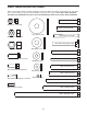
PART IDENTIFICATION CHART Refer to the drawings below to identify small parts used in assembly. The number in parentheses by each drawing is the key number of the part, from the PART LIST near the end of this manual. Note: Some small parts may have been preattached. If a part is not in the hardware kit, check to see if it has been preattached.
ASSEMBLY • Place all parts in a cleared area and remove the packing materials. Do not dispose of the packing materials until assembly is completed. Make Assembly Easier Everything in this manual is designed to ensure that the weight system can be assembled successfully by almost anyone. By setting aside plenty of time, assembly will go smoothly. • For help identifying small parts, use the PART IDENTIFICATION CHART on page 5.
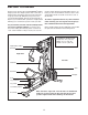
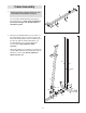
1. Frame Assembly 1 Before beginning assembly, make sure you understand the information on page 6. 1 Insert four M8 x 63mm Carriage Bolts (64) up through the Base (1). Note: It may be helpful to place a piece of tape over the bolt heads to hold them in place. 64 64 2. Orient the two Weight Guides (21) as shown, so the indicated holes are closer to the lower ends.
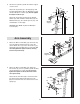
3. Attach the Front Leg (7) to the Base (1) with the two M8 x 63mm Carriage Bolts (64) and two M8 Nylon Locknuts (58). Do not tighten the Nylon Locknuts yet. 3 7 Upward 33 Attach the Leg Bumper (60) to the Front Leg (7) with an M4 x 20mm Self-tapping Screw (69) and an M4 Washer (33). Make sure that the end of the Leg Bumper is pointing upward. 58 60 69 58 1 64 4. Attach the Seat Frame (6) to the Upright (3) with two M8 x 65mm Bolts (68), two M8 Washers (59), and two M8 Nylon Locknuts (58).
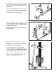
6. Orient the Top Frame (4) with the welded support on the bottom. 6 Attach the Top Frame (4) to the Upright (3) with two M8 x 65mm Bolts (68), two M8 Washers (59), and two M8 Nylon Locknuts (58). Do not tighten the Nylon Locknuts yet. 68 4 Attach the Top Frame (4) between the Weight Guides (21) with an M10 x 155mm Bolt (74), two M10 Washers (57), two 19mm Spacers (76), and an M10 Nylon Locknut (56). Welded Support See steps 2–4, and 6. Tighten the M8 Nylon Locknuts (58).
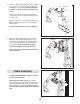
9. Grease an M10 x 51mm Bolt (66). Attach a Cable Pivot (39) to the Left Arm (10) with the Bolt and an M10 Nylon Locknut (56). Do not overtighten the Nylon Locknut; the Cable Pivot must pivot easily. 9 66 9 Wet the inside of a Large Foam Pad (42) with soapy water. Slide the Large Foam Pad onto the Left Arm (10). Grease 39 56 Attach a Handle (11) to the Left Arm (10) with two M10 x 25mm Button Screws (77) and two M10 Washers (57). 10 42 11 57 Assemble the Right Arm (9) in the same way. 57 10.
12. Route the Arm Cable (54) over a V-pulley (46). Attach the V-pulley, a Large Cable Trap (50), two Full Guards (41), and an M10 Washer (57) to the Upright (3) with an M10 x 63mm Bolt (75) and an M10 Nylon Locknut (56). Make sure that the Cable Trap is oriented to hold the Cable in the groove of the V-pulley. 12 13. Route the Arm Cable (54) under a 90mm Pulley (48). Attach the Pulley and two Half Guards (43) to the Double U-bracket (63) with an M10 x 46mm Bolt (81) and an M10 Nylon Locknut (56).
15. Grease an M8 x 22mm Shoulder Bolt (65). Attach the Arm Cable (54) to the indicated Cable Pivot (39) with the Shoulder Bolt and an M8 Nylon Locknut (58). Make sure that the cable end can pivot easily on the Shoulder Bolt. 15 Grease 65 16. Identify the Low Cable (53). Route the Cable through the Leg Lever (8) and the Front Leg (7).
18. Route the Low Cable (53) under a 90mm Pulley (48) and through the Upright (3). Attach the Pulley inside the Upright with an M10 x 67mm Bolt (71), two M10 Washers (57), two 12mm Spacers (52), and an M10 Nylon Locknut (56). 18 56 57 53 19. Route the Low Cable (53) over a 90mm Pulley (48). Attach the Pulley and two Half Guards (43) to the Double U-bracket (63) with an M10 x 46mm Bolt (81) and an M10 Nylon Locknut (56). Make sure that the Half Guards are on the outside of the U-bracket as shown.
21. Attach the Low Cable (53) to the U-bracket (45) with an M8 Washer (59) and an M8 Nylon Locknut (58). See the inset drawing. Do not overtighten the Nylon Locknut; it should be threaded onto the end of the Cable so that only two threads are showing above the Nylon Locknut. 21 58 59 58 45 22. Identify the High Cable (55). Route the Cable up through the Top Frame (4) and over a 90mm Pulley (48).
25. Route the High Cable (55) up through the Top Frame (4) and over a 90mm Thin Pulley (47). Attach the Pulley inside the Top Frame with the M10 x 67mm Bolt (71) used in step 23, an 11mm Spacer (49), an M10 Washer (57), and an M10 Nylon Locknut (56). 25 56 57 26. Route the High Cable (55) over a 90mm Pulley (48) and down through the Top Frame (4). Attach the Pulley inside the Top Frame with an M10 x 67mm Bolt (71), two M10 Washers (57), two 12mm Spacers (52), and an M10 Nylon Locknut (56). 26 27.
Seat Assembly 28 28. Attach the Backrest (16) to the Upright (3) with two M6 x 63mm Screws (70) and two M6 Washers (80). 3 16 80 70 80 70 29. Attach the Seat (15) to the Seat Frame (6) with four M6 x 16mm Screws (62) as shown. 29 15 6 62 30. Attach the Lock Plate (73) to the Front Leg (7) with an M10 x 70mm Bolt (72), an M10 Washer (57), and an M10 Nylon Locknut (56). Do not overtighten the Nylon Locknut; the Lock Plate must pivot easily.
31. Insert the Pad Tube (29) into the Front Leg (7). Slide two Small Foam Pads (28) onto the ends of the Pad Tube. 31 29 28 Slide two Small Foam Pads (28) onto the Leg Lever (8). 28 32. Attach the Curl Pad (14) to the Curl Post (13) with two M6 x 16mm Screws (62). 7 28 8 28 32 14 13 62 33. Make sure that all parts have been properly tightened. The use of the remaining parts will be explained in ADJUSTMENT, beginning on page 18.
ADJUSTMENT This section explains how to adjust the weight system. See the EXERCISE GUIDELINES on page 23 for important information about how to get the most benefit from your exercise program. Also, refer to the accompanying exercise guide to see the correct form for each exercise. Make sure all parts are properly tightened each time the weight system is used. Replace any worn parts immediately. The weight system can be cleaned with a damp cloth and a mild, non-abrasive detergent. Do not use solvents.
USING THE LOCK LEVER Before using the low pulley station, engage the Leg Lever Pin (38) into the Leg Lever (8) and the Lock Plate (73). 38 8 73 ARM CONVERSION To use the Arms (9, 10) as butterfly arms, insert the Arm Pins (40) into the holes in the Upright (3) and the Pivot Frame (5) as shown. To use the Arms (9, 10) as press arms, insert the Arm Pins (40) into the holes in the Pivot Frame (5) and the Arms.
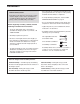
LOCKING THE WEIGHT STACK Lock the weight stack by inserting the Lock Pin (18) through a Weight Guide (21) and securing the Lock (17) onto the Lock Pin. 21 17 18 WEIGHT RESISTANCE CHART The chart below shows the approximate weight resistance at each exercise station. The numbers in the left column refer to the 12.5-lb. weights. Note: The weight resistance shown for the butterfly arm station is for each arm.
CABLE DIAGRAM The diagram below shows the proper routing of the cables. The numbers in each drawing show the proper route of that cable. Use the diagram to make sure that the cables, cable traps, pulleys, and guards are assembled correctly. If the cables are not assembled correctly, the weight system will not function properly and damage may occur. Make sure that the cable traps do not touch or bind the cables. 4 High Cable (55) Length: 9 ft. 6 in. (290 cm) 2 5 1 6 3 6 Low Cable (53) Length: 10 ft.
MAINTENANCE Make sure that all parts are properly tightened each time the weight system is used. Replace any worn parts immediately. The weight system can be cleaned with a damp cloth and a mild, non-abrasive detergent. Do not use solvents. TIGHTENING THE CABLES Woven cable, the type of cable used on the weight system, can stretch slightly when it is first used. If there is slack in the cables before resistance is felt, the cables should be tightened.
EXERCISE GUIDELINES THE FOUR BASIC TYPES OF WORKOUTS Muscle Building To increase the size and strength of your muscles, push them close to their maximum capacity. Your muscles will continually adapt and grow as you progressively increase the intensity of your exercise. You can adjust the intensity level of an individual exercise in two ways: • by changing the amount of resistance used • by changing the number of repetitions or sets performed.
COOLING DOWN The repetitions in each set should be performed smoothly and without pausing. The exertion stroke of each repetition should last about half as long as the return stroke. Proper breathing is important. Exhale during the exertion stroke of each repetition and inhale during the return stroke. Never hold your breath. End each workout with 5 to 10 minutes of stretching. Include stretches for both your arms and legs. Move slowly as you stretch and do not bounce.
PART LIST—Model No. WESY1938.0 Key No. 1 2 3 4 5 6 7 8 9 10 11 12 13 14 15 16 17 18 19 20 21 22 23 24 25 26 27 28 29 30 31 32 33 34 35 36 37 38 39 40 41 42 43 Qty.
EXPLODED DRAWING A—Model No. WESY1938.
EXPLODED DRAWING B—Model No. WESY1938.
ORDERING REPLACEMENT PARTS To order replacement parts, please see the front cover of this manual.