WEICHAI & PSI SERVICE MANUALS AVAILABLE ONLINE AT FLYPARTSGUY.COM Assembly & Disassembly Manual Gas Engine Model: WP6GNA WEICHAI AMERICA CORP. GET YOUR WEICHAI & AFTERMARKET SERVICE PARTS AT FLYPARTSGUY.
WEICHAI & PSI SERVICE MANUALS AVAILABLE ONLINE AT FLYPARTSGUY.COM Weichai America Corp. Purpose This manual is intended to inform customers on how to assemble and disassemble the Weichai America 6 Liters naturally aspirated engine. This document will be provided to customer so they can incorporate this information into their manuals and service documents. Maintenance Providers Maintenance and repair services may be performed by you or any qualified engine service provider that you choose.
WEICHAI & PSI SERVICE MANUALS AVAILABLE ONLINE AT FLYPARTSGUY.COM Weichai America Corp. Table of Contents 1 Disassembly & Assembly of Engine ..................................................................................... 5 1.1 Safety Precautions............................................................................................................ 5 1.2 Environmental Protection Measures ................................................................................. 5 1.
WEICHAI & PSI SERVICE MANUALS AVAILABLE ONLINE AT FLYPARTSGUY.COM Weichai America Corp. 7.2 Fan Assembly and Disassembly ..................................................................................... 27 7.3 Thermostat Disassembly and Assembly ......................................................................... 28 7.4 Water Pump Assembly and Disassembly ....................................................................... 29 8 Front Cover Components ...........................................
WEICHAI & PSI SERVICE MANUALS AVAILABLE ONLINE AT FLYPARTSGUY.COM Weichai America Corp. 11.4 Assembly and disassembly of crank-rod mechanism. ........................................... 61 11.5 Assembly and disassembly of piston-rod assembly .............................................. 61 11.6 Assembly and disassembly of crankshaft system ................................................. 65 11.7 Assembly and disassembly of crankshaft bearing shell ........................................ 68 11.
WEICHAI & PSI SERVICE MANUALS AVAILABLE ONLINE AT FLYPARTSGUY.COM Weichai America Corp. 1 Disassembly & Assembly of Engine 1.1 Safety Precautions Please strictly comply with instructions in this manual to safely and properly disassemble and assemble the engine. 1.2 Environmental Protection Measures Please comply with relevant laws and regulations on environmental protection when handling oil and hydrocarbon waste. For further instructions please contact your local officials. 1.
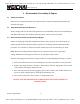
WEICHAI & PSI SERVICE MANUALS AVAILABLE ONLINE AT FLYPARTSGUY.COM Weichai America Corp. 2 Fuel System 2.1 Fuel System Assembly and Disassembly 2.1.1 Fuel System Exploded View Fig. 2-1 Exploded view of gas supply system 2.1.2 Fuel System Disassembly Procedure 1. Remove ECU. 2. Remove the LPG intake system. 3. Remove the NG intake system. 4. Remove the electronic pressure regulating system. 2.1.3 Fuel System Assembly Procedure Reverse the Disassembly Procedure (2.1.2) to assemble the Gas Supply System.
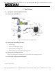
WEICHAI & PSI SERVICE MANUALS AVAILABLE ONLINE AT FLYPARTSGUY.COM Weichai America Corp. 2.2 LPG Intake System Assembly and Disassembly 2.2.1 LPG Intake System Exploded View Fig. 2-2 Exploded view of LPG supply system 2.2.2 LPG Intake System Disassembly Procedure 1. Remove the clamps from the gas hose. Separate the hose from the NG intake system. 2. Remove the nuts and washers bolting the LPG bracket to the cylinder head assembly.
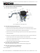
WEICHAI & PSI SERVICE MANUALS AVAILABLE ONLINE AT FLYPARTSGUY.COM Weichai America Corp. 2. Check the coolant fittings and hoses for leaks. 2.3 NG Shut-Off Valve Assembly and Disassembly 2.3.1 NG Shut-Off Valve Exploded View Fig. 2-3 Exploded view of electromagnetic valve 2.3.2 NG Shut-Off Valve Disassembly Procedure 1. Remove the bolts and nuts bolting the NG shut-off valve to the gas pipe joint. 2. Remove the bolts and nuts bolting the NG bracket to the NG shut-off valve. Remove the NG shut-off valve.
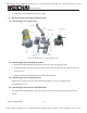
WEICHAI & PSI SERVICE MANUALS AVAILABLE ONLINE AT FLYPARTSGUY.COM Weichai America Corp. 2.4 Electronic Pressure Regulator (EPR) Assembly and Disassembly 2.4.1 EPR Exploded View Fig. 2-4 Exploded view of electronic pressure regulating valve 2.4.2 EPR Disassembly Procedure 1. Remove the socket head bolts and washers bolting the gas pipe joint to the EPR. 2. Remove the hex bolts and washers bolting the EPR to the mixer. Remove the EPR. 2.4.3 EPR Assembly Procedure Reverse the Disassembly Procedure (2.4.
WEICHAI & PSI SERVICE MANUALS AVAILABLE ONLINE AT FLYPARTSGUY.COM Weichai America Corp. Fig. 2-5 Exploded view of mixer No. Part Name No. Part Name No. Part Name 1 Screws 6 Diaphragm 11 Spring 2 Mixer Cover 7 Ring 12 Adjustment Screw 3 Spring 8 Air Fuel Regulator Valve 13 Gasket 4 Screws 9 Diaphragm Assembly 5 Board 10 Mixer body 2.5.2 Mixer Diaphragm Disassembly Procedure 1. Remove the screws on the mixer cover. Remove the mixer cover. 2. Remove the diaphragm spring. 3.
WEICHAI & PSI SERVICE MANUALS AVAILABLE ONLINE AT FLYPARTSGUY.COM Weichai America Corp. Reverse the Disassembly Procedure (2.5.2) to assemble the Mixer Diaphragm. 2.5.4 Mixer Diaphragm Inspection and Maintenance If gas flow is insufficient: 1. Rotate the adjustment screw clockwise to increase the flow of gas. 2. Replace the gas diaphragm with a biogas diaphragm to increase the flow of gas. To replace the mixer diaphragm according to maintenance specifications: 1. Remove the old mixer diaphragm. 2.
WEICHAI & PSI SERVICE MANUALS AVAILABLE ONLINE AT FLYPARTSGUY.COM Weichai America Corp. 3 Intake and Exhaust System 3.1 Intake and Exhaust System Assembly and Disassembly 3.1.1 Intake and Exhaust System Exploded View Fig. 3-1 Exploded view of intake and exhaust system Fig. 3-2 Exploded view of intake elbow Revision: August 2019 12 GET YOUR WEICHAI & AFTERMARKET SERVICE PARTS AT FLYPARTSGUY.
WEICHAI & PSI SERVICE MANUALS AVAILABLE ONLINE AT FLYPARTSGUY.COM Weichai America Corp. 3.1.2 Intake and Exhaust System Disassembly Procedure 1. Loosen the clamps on the air filter elbow, elbow pipe breather connection, and the mixer hose. Remove the air filter elbow, elbow pipe, and mixer hose. 2. Remove the hex bolts bolting the air filter to the air filter bracket. Remove the air filter 3. Remove the socket head bolts bolting the throttle adapter to the mixer. Remove the mixer.
WEICHAI & PSI SERVICE MANUALS AVAILABLE ONLINE AT FLYPARTSGUY.COM Weichai America Corp. 3.2 Intake Manifold Assembly and Disassembly 3.2.1 Intake Manifold Exploded View Fig. 3-3 Exploded view of intake manifold 3.2.2 Intake Manifold Disassembly Procedure 1. Remove the nuts bolting the intake manifold to the engine block. Remove the intake manifold and gaskets. 2. Remove the bolts bolting the cover plates to the intake manifold. Remove the cover plates and the gaskets. 3.2.
WEICHAI & PSI SERVICE MANUALS AVAILABLE ONLINE AT FLYPARTSGUY.COM Weichai America Corp. Fig. 3-4 Exploded view of exhaust manifold 3.3.2 Exhaust Manifold Disassembly Procedure CAUTION: All parts of the exhaust manifold and exhaust elbow will be extremely hot after engine operation. 1. Remove the heat shield bolts and the heat shield. 2. Untie the exhaust elbow insulation ties. Remove the exhaust elbow insulation with the ties. 3. Loosen and remove the oxygen sensor. 4.
WEICHAI & PSI SERVICE MANUALS AVAILABLE ONLINE AT FLYPARTSGUY.COM Weichai America Corp. 3. Do not reuse exhaust manifold attachment bolts more than twice. 3.3.4 Exhaust Manifold Inspection and Maintenance 1. Check for cracks in the exhaust manifold and deformations in the exhaust elbow flange. Replace the exhaust manifold and exhaust elbow if necessary. 2. Check the exhaust elbow flange for any air leakage. Replace the exhaust elbow gasket if necessary. 3.
WEICHAI & PSI SERVICE MANUALS AVAILABLE ONLINE AT FLYPARTSGUY.COM Weichai America Corp. Fig. 3-6 Exploded view of ignition system 3.4.2 Ignition System Disassembly Steps 1. Unplug the wiring harness connector from the ECU and ignition coil. 2. Remove ignition coil bolts and ignition coils. 3. Remove spark plugs. 4. Remove signal generator. See Signal Generator Assembly and Disassembly (3.5) for details. 3.4.3 Ignition System Assembly Steps Reverse the Disassembly Procedure (3.4.
WEICHAI & PSI SERVICE MANUALS AVAILABLE ONLINE AT FLYPARTSGUY.COM Weichai America Corp. Fig. 3-7 Exploded view of signal generator 3.5.2 Signal Generator Disassembly Procedure 1. Remove the connecting bolts of the pump gear and signal generator. 2. Remove the hex nuts between signal generator flange and engine block. 3. Remove the signal generator from the engine. 3.5.3 Signal Generator Assembly Procedure 1. Adjust the crankshaft to TDC: the first cylinder piston should be in its compression stroke.
WEICHAI & PSI SERVICE MANUALS AVAILABLE ONLINE AT FLYPARTSGUY.COM Weichai America Corp. 3.6 Engine Control Unit (ECU) Assembly and Disassembly 3.6.1 ECU Exploded View Fig. 3-8 Exploded view of ECU 3.6.2 ECU Disassembly Procedure 1. Remove the fuse box bolts. Remove the fuse box from the bracket. 2. Remove the Harness ECU Connection from the ECU. 3. Remove the ECU bolts. Remove the ECU from the bracket. 3.6.3 ECU Assembly Procedure Reverse the Disassembly Procedure (3.6.2) to assemble the ECU 3.6.
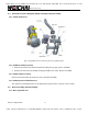
WEICHAI & PSI SERVICE MANUALS AVAILABLE ONLINE AT FLYPARTSGUY.COM Weichai America Corp. electromagnetic torque. The ring gear mechanism drives the starting engine rotation. The starter motor’s main components are the DC motor, one-way clutch, reduction gear train, electromagnetic switches, and the starter relay. See the dismantled starting system in Fig. 4-1. Fig. 4-1 Exploded view of starting system 4.1.2 Starting System Disassembly Procedure 1. Fully disconnect all harness connections from the starter.
WEICHAI & PSI SERVICE MANUALS AVAILABLE ONLINE AT FLYPARTSGUY.COM Weichai America Corp. 5 Engine Accessory System 5.1 Engine Accessory System Assembly and Disassembly 5.1.1 Engine Accessory System Exploded View The engine accessory system consists primarily of the belt and alternator. Fig. 5-1 Exploded view of engine accessory system 5.1.2 Engine Accessory System Disassembly Refer to the Engine Accessory System Exploded View (Figure 5-1) for disassembly details. 1.
WEICHAI & PSI SERVICE MANUALS AVAILABLE ONLINE AT FLYPARTSGUY.COM Weichai America Corp. Fig. 5-2 Exploded view of generator 5.2.2 Alternator Disassembly Procedure 1. Remove the alternator lock nut to loosen the belt if it has not already been removed. Remove the belt from the alternator pulley. 2. Remove the ground cable and the battery cable from the alternator. 3. Remove all bolts bolting the alternator to the bracket. Remove the alternator from its bracket. 4.
WEICHAI & PSI SERVICE MANUALS AVAILABLE ONLINE AT FLYPARTSGUY.COM Weichai America Corp. 6 Closed Crankcase Ventilation (CCV) Breather System Assembly and Disassembly 6.1 CCV Breather System Assembly and Disassembly 6.1.1 CCV Breather System Exploded View Air Inlet Air Outlet Oil Return Fig. 6-1 Exploded view of CCV breather system No. Name No. Name No. Name No.
WEICHAI & PSI SERVICE MANUALS AVAILABLE ONLINE AT FLYPARTSGUY.COM Weichai America Corp. 7 Hex Nut 17 Rubber Hose 27 Clamp 8 Clamp 18 Formed Hose 28 Bolt 9 Bracket 19 Bolt 29 Oil Return Pipe 10 Hex Bolt 20 Washer 30 Nut 6.1.2 CCV Breather System Disassembly Procedure 1. Loosen the clamps on the air outlet. Remove all air outlet formed and rubber hoses. 2. Loosen the clamps on the oil return pipe. Remove the oil return pipe and hose. 3. Loosen the clamps on the air inlet.
WEICHAI & PSI SERVICE MANUALS AVAILABLE ONLINE AT FLYPARTSGUY.COM Weichai America Corp. Fig. 6-2 Exploded view of CCV breather Fig. 6-3 Schematic diagram of disassembly 6.2.2 CCV Breather Disassembly Open the top cover of the breather by tool or hand. Remove the breather filter element. 6.2.3 CCV Breather Assembly 1. Clean the inside of the breather. Insert a new breather filter element. 2. Screw the top cover back onto the breather. 6.2.
WEICHAI & PSI SERVICE MANUALS AVAILABLE ONLINE AT FLYPARTSGUY.COM Weichai America Corp. 7 Cooling System 7.1 Cooling System Disassembly and Assembly 7.1.1 Cooling System Exploded View The cooling system ensures that the engine can operate at the proper operating temperature. Forced circulation cooling is most effective at keeping the engine within the normal operating temperature range. The cooling system primarily consists of the water pump, fan, expansion water tank, water tank and thermostat. Fig.
WEICHAI & PSI SERVICE MANUALS AVAILABLE ONLINE AT FLYPARTSGUY.COM Weichai America Corp. 7. Remove the middle cushion block of water pump. 7.1.3 Cooling System Assembly Procedure Reverse the Disassembly Procedure (7.1.2) to assemble the Cooling System. 7.2 Fan Assembly and Disassembly 7.2.1 Fan Exploded View Fig. 7-2 Exploded view of fan 7.2.2 Fan Disassembly Procedure 1. Loosen the six fixing bolts on the fan. Remove the bolts, washers, and fan. 2.
WEICHAI & PSI SERVICE MANUALS AVAILABLE ONLINE AT FLYPARTSGUY.COM Weichai America Corp. 7.3 Thermostat Disassembly and Assembly 7.3.1 Thermostat Exploded View Fig. 7-3 Exploded view of thermostat 7.3.2 Thermostat Disassembly Procedure 1. Loosen the clamps around the hose connecting the water pipe and thermostat. Remove the hose. 2. Loosen the clamps around the hose connecting the thermostat and water pump. Remove the hose and thermostat. 7.3.
WEICHAI & PSI SERVICE MANUALS AVAILABLE ONLINE AT FLYPARTSGUY.COM Weichai America Corp. 7.4 Water Pump Assembly and Disassembly 7.4.1 Water Pump Exploded View Fig. 7-4 Exploded view of water pump 7.4.2 Water Pump Disassembly Procedure 1. Remove the water pump pulley. 2. Remove thermostat connecting hose and clamps. 3. Remove the hexagon bolts on the pump. 4. Remove water pump, gasket and middle cushion block. 7.4.3 Water Pump Assembly Procedure Reverse the Disassembly Procedure (7.4.
WEICHAI & PSI SERVICE MANUALS AVAILABLE ONLINE AT FLYPARTSGUY.COM Weichai America Corp. 8 Front Cover Components 8.1 Torque Vibration Damper and Crankshaft Pulley Assembly and Disassembly 8.1.1 Torque Vibration Damper and Crankshaft Pulley Exploded View Fig. 8-1 Exploded view of damper, pulley, and hub 8.1.2 Torque Vibration Damper and Crankshaft Pulley Disassembly Procedure 1. Remove the six damper fastening bolts. Remove the crankshaft pulley and torque vibration damper in the order listed. 2.
WEICHAI & PSI SERVICE MANUALS AVAILABLE ONLINE AT FLYPARTSGUY.COM Weichai America Corp. Tightening torque: 60~70Nm; Test value: 65~80Nm. 8.1.4 Torque Vibration Damper and Crankshaft Pulley Inspection and Maintenance 1. Check the crankshaft pulley for any damage and distortion. Replace if necessary. 2. Check the torque vibration damper and hub for damage. Replace either if necessary. 3. Check the hub fastening bolts and damper fastening bolts for damaged. Replace any if necessary. 8.
WEICHAI & PSI SERVICE MANUALS AVAILABLE ONLINE AT FLYPARTSGUY.COM Weichai America Corp. 2 Bolt 11 Bolt 3 Front Oil Seal 12 Bolt 4 Shaft 13 Bolt 5 Intermediate Shaft 14 Oil Fill Plug 6 Intermediate Gear 15 Washer 7 Plate 16 Stud 8 Bolt 17 Nut 9 Bolt 8.2.2 Gear Housing Disassembly Procedure 1. Remove the intermediate gear. 2. Remove the front cover plate (See Key Point 1 under section 8.2.4). 3. Remove the front oil seal (See Key Point 2 under section 8.2.4). 8.2.
WEICHAI & PSI SERVICE MANUALS AVAILABLE ONLINE AT FLYPARTSGUY.COM Weichai America Corp. Fig. 8-3 Locating pin installation for Gear Housing (2) Apply sealant on the sealing surface of the Gear Housing. Ensure that the sealant is evenly distributed and continuous. Fig. 8-4 Sealing surface of Gear Housing (3) Place the gear housing with alignment pins in the pin holes. Knock the cover edge gently with a nylon rod such that the cover and engine block can fit together closely.
WEICHAI & PSI SERVICE MANUALS AVAILABLE ONLINE AT FLYPARTSGUY.COM Weichai America Corp. Fig. 8-5 Gear Housing installation (4) Place the bolts with gaskets in their corresponding holes. Tighten them with a pneumatic impact wrench and an open-end wrench. Key Point 2: Assembling: Oil seals and seal rings should be checked before assembling. Ensure there is no damage or dirt.
WEICHAI & PSI SERVICE MANUALS AVAILABLE ONLINE AT FLYPARTSGUY.COM Weichai America Corp. Fig. 8-6 Exploded view of intermediate gear 8.3.2 Intermediate Gear Disassembly Procedure 1. Locate the four M10 bolts to be removed. 2. Remove four bolts and the washer. 3. Insert a M8 bolt into the pin-shaft. Pull the pin-shaft out along this bolt. Take care to ensure that the intermediate gear does not slide off and get damaged. 8.3.3 Intermediate Gear Assembly Procedure 1.
WEICHAI & PSI SERVICE MANUALS AVAILABLE ONLINE AT FLYPARTSGUY.COM Weichai America Corp. or pin-shaft for any wear. Check the oil passage for any blockage. 9 Cylinder Heads and Valves 9.1 Lifting Lugs Assembly and Disassembly 9.1.1 Lifting Lugs Exploded View Fig. 9-1 Exploded view of lifting lugs 9.1.2 Lifting Lugs Disassembly Procedure Loosen and remove the lifting lugs. 9.1.3 Lifting Lugs Assembly Procedure Check the lifting lugs and standoffs for any damaged threads.
WEICHAI & PSI SERVICE MANUALS AVAILABLE ONLINE AT FLYPARTSGUY.COM Weichai America Corp. Fig. 9-2 Exploded view of cylinder head cover 9.2.2 Cylinder Head Cover Disassembly Procedure 1) Loosen the cylinder head cover bolts. Remove the bolts and the washers. 2) Pull the covers up vertically to remove them. Remove all gaskets. 9.2.3 Cylinder Head Cover Assembly Procedure 1) Use new cylinder head cover gaskets for all assemblies and inspect them for any defects or damage prior to assembly.
WEICHAI & PSI SERVICE MANUALS AVAILABLE ONLINE AT FLYPARTSGUY.COM Weichai America Corp. 9.3 Rocker and Rocker Shaft Assembly and Disassembly 9.3.1 Rocker and Rocker Shaft Exploded View Fig. 9-3 Exploded view of rocker and rocker shaft 9.3.2 Rocker and Rocker Shaft Disassembly Procedure 1. Rotate the crankshaft to ensure that the rocker moves smoothly. 2. Measure each valve clearance, and check any changes in valve clearance. 3.
WEICHAI & PSI SERVICE MANUALS AVAILABLE ONLINE AT FLYPARTSGUY.COM Weichai America Corp. ⑤ Install valve pushrod, refer to assembly of valve pushrod for details; ① Pre-tighten rocker seat, align rocker adjusting screw socket head to valve pushrod round head, tighten the hexagon bolts to 40~45Nm.
WEICHAI & PSI SERVICE MANUALS AVAILABLE ONLINE AT FLYPARTSGUY.COM Weichai America Corp. Fig. 9-4 Exploded view of tappet and pushrod 9.4.2 Tappet and Pushrod Disassembly Procedure 1. After removing rockers and rocker shafts, pull the pushrods out vertically. 2. After removing camshaft, directly take out valve tappet, place them orderly; 9.4.3 Tappet and Pushrod Assembly Procedure 1. Check valve tappets and pushrod, replace them if necessary.
WEICHAI & PSI SERVICE MANUALS AVAILABLE ONLINE AT FLYPARTSGUY.COM Weichai America Corp. 2. Ensure that the oil channels of valve tappet and pushrod are smooth. 3. Ensure that the pushrod is not crooked. Check wear condition on the outside surface. 4. Ensure that the two ends of the pushrod are not worn. 5. Ensure that the valve tappet surface and undersurface are not worn. 6. Ensure that the valve tappet inner socket head is not worn. 9.5 Cylinder Heads Assembly and Disassembly 9.5.
WEICHAI & PSI SERVICE MANUALS AVAILABLE ONLINE AT FLYPARTSGUY.COM Weichai America Corp. 3. Remove the cylinder head gasket. If more than one cylinder head gasket needs to be disassembled, mark the cylinder number on the gaskets for reference. 4. Remove the intake and exhaust valve module. Refer to disassembly of valve mechanism (9.6) for details 5. Remove the valve seal. Valve seals can’t be reused. 9.5.3 Cylinder Heads Assembly Procedure 1. Insert the seal valve into the valve guide pipe. 2.
WEICHAI & PSI SERVICE MANUALS AVAILABLE ONLINE AT FLYPARTSGUY.COM Weichai America Corp. Clean the cylinder head, focusing on the combustion chamber surface, valve seat, intake and exhaust valves, and intake and exhaust passages. Remove the carbon deposits and mucilage glue, and check the surface condition. 1. Appearance Inspection: Check the cylinder cover for any discoloration or cracks. If any cracks are discovered, a leak test should be done. 2.
WEICHAI & PSI SERVICE MANUALS AVAILABLE ONLINE AT FLYPARTSGUY.COM Weichai America Corp. 3. Clearance between valve rod and valve guide pipe: Internal surface of valve guide pipe is the contacting surface between valve rod and valve guide pipe, if clearance between valve rod and valve guide pipe exceeds allowed value due to abrasion, then the guide effect will at state, which may affect reliability of the engine. The inner diameter of guide pipe can be measured with an inside micrometer, as shown in Fig.
WEICHAI & PSI SERVICE MANUALS AVAILABLE ONLINE AT FLYPARTSGUY.COM Weichai America Corp. Fig. 9- 9 Exploded view of valve 9.6.2 Steps to disassemble valve ① Depress valve springs with vale spring compressor or valve overhead plier or other tools, take out valve lock clamp, upper valve spring seat and lower valve spring seat and valve springs orderly; ② Take valve out of valve seat. 9.6.3 Steps to assemble valve A valve with severe wear or carbon deposit or sintering should be replaced.
WEICHAI & PSI SERVICE MANUALS AVAILABLE ONLINE AT FLYPARTSGUY.COM Weichai America Corp. 9.6.4 Inspection and maintenance of valve ① Check whether valve rod and its end faces are worn; ② Check whether valve conical surface is worn or damaged; ③ Check valve conical surface and retainer end faces for carbon deposit; Revision: August 2019 46 GET YOUR WEICHAI & AFTERMARKET SERVICE PARTS AT FLYPARTSGUY.
WEICHAI & PSI SERVICE MANUALS AVAILABLE ONLINE AT FLYPARTSGUY.COM Weichai America Corp. 10 Oil & Lubrication System 10.1 Assembly and disassembly of oil sump. 10.1.1 Exploded view of oil sump. Fig. 10-1 Exploded view of oil sump 10.1.2 Steps to disassemble oil sump. ① Turn over engine to keep oil sump upward (key point 1) ② Remove fixing bolts of oil sump. ③ Remove oil sump. ④ Remove the combination gasket and magnetic screw plug assembly. 10.1.3 Steps to assemble oil sump.
WEICHAI & PSI SERVICE MANUALS AVAILABLE ONLINE AT FLYPARTSGUY.COM Weichai America Corp. (1) Apply sealant on fitting surface of engine block and partially apply sealant on oil sump, place sealing gasket on the fitting surface. (2) Lift and place oil sump, be careful and avoid crashing the fitting surface. (3) Place bolts and gaskets, and tighten the bolts with pneumatic impact wrench to 20~35.5Nm. 10.2 Disassembly and Assembly of Engine Oil Strainer 10.2.1 Exploded View of Engine Oil Strainer Fig.
WEICHAI & PSI SERVICE MANUALS AVAILABLE ONLINE AT FLYPARTSGUY.COM Weichai America Corp. 10.3 Disassembly and Assembly of Lubricating System 10.3.1 Exploded View of Lubricating System Fig. 10-3 Exploded view of lubricating system 10.3.2 Steps to Disassemble Lubricating System ① Remove oil sump, refer to disassembly of oil sump for details. ② Remove gearbox, refer to disassembly of gearbox for details. ③ Remove engine oil pump. ④ Remove the cooling module of engine oil filter. 10.3.
WEICHAI & PSI SERVICE MANUALS AVAILABLE ONLINE AT FLYPARTSGUY.COM Weichai America Corp. Fig. 10- 4 Exploded view of piston nozzle 10.4.2 Steps to disassemble piston nozzle. ① Remove the hexagon bolt (key point 1) ② Remove the piston nozzle (key point 2) 10.4.3 Steps to assemble piston nozzle Assembling steps are contrary to disassembling ones. 10.4.4 Inspection and maintenance of piston nozzle.
WEICHAI & PSI SERVICE MANUALS AVAILABLE ONLINE AT FLYPARTSGUY.COM Weichai America Corp. 10.5 Disassembly and Assembly of Engine Oil Pump 10.5.1 Exploded View of Engine Oil Pump Fig. 10-5 Exploded view of engine oil pump 10.5.2 Steps to Disassemble Engine Oil Pump Remove the two hexagon bolts and self-locking nut, take down engine oil pump, as shown in Fig. 10-5. 10.5.3 Steps to Assemble Engine Oil Pump 1) Check the pump before assembling, make sure there is no manufacturing defect and damage.
WEICHAI & PSI SERVICE MANUALS AVAILABLE ONLINE AT FLYPARTSGUY.COM Weichai America Corp. Fig. 10-6 Exploded view of engine oil filter 10.6.2 Steps to Disassemble Engine Oil Filter Remove the filter with dedicated tool, as shown in Fig. 10-6. 10.6.3 Steps to Assemble Engine Oil Filter 1) Check the O-shape seal ring of engine oil filter before assembling, make sure there is no manufacturing defect and damage, replace the O-ring if necessary. 2) Tighten the filter according to the requirements on filter cap.
WEICHAI & PSI SERVICE MANUALS AVAILABLE ONLINE AT FLYPARTSGUY.COM Weichai America Corp. Fig. 10-7 Exploded view of engine oil cooler 10.7.2 Steps to Disassemble Engine Oil Cooler Loose the connecting bolts and take down the cooler, as shown in Figure 10-7. 10.7.3 Steps to Assemble Engine Oil Cooler ①Check the cooler before assembling, make sure there is no manufacturing defect and damage. ②Clean up the fitting surface between engine oil cooler and filter seat.
WEICHAI & PSI SERVICE MANUALS AVAILABLE ONLINE AT FLYPARTSGUY.COM Weichai America Corp. Fig. 10-8 Exploded View of Main Oil Gallery Pressure Limiting Valve 10.8.2 Steps to Disassemble Main Oil Gallery Pressure Limiting Valve Screw off main oil gallery pressure limiting valve, as shown in Fig. 10-8 10.8.3 Steps to Assemble Main Oil Gallery Pressure Limiting Valve ①Check the valve before assembling, make sure there is no manufacturing defect and damage.
WEICHAI & PSI SERVICE MANUALS AVAILABLE ONLINE AT FLYPARTSGUY.COM Weichai America Corp. Fig. 10-9 Exploded view of deputy oil pressure limiting valve 10.9.2 Steps to Disassemble Deputy Oil Pressure Limiting Valve Screw off and take down deputy oil pressure limiting valve, as shown in Fig. 10-9. 10.9.
WEICHAI & PSI SERVICE MANUALS AVAILABLE ONLINE AT FLYPARTSGUY.COM Weichai America Corp. Fig. 11-1 Exploded view of flywheel housing 11.1.2 Steps to disassemble flywheel housing ① Remove fixing bolts of flywheel housing (Key point 1). ② Remove speed sensor ③ Remove fixing bolts of monitoring window cap on flywheel housing, take down the cap; ④ Remove flywheel housing (key point 2). 11.1.3 Steps to assemble flywheel housing. Assembling steps are contrary to disassembling ones. 11.1.
WEICHAI & PSI SERVICE MANUALS AVAILABLE ONLINE AT FLYPARTSGUY.COM Weichai America Corp. flywheel housing and engine block. Bolts and tools: M10-10.9 hexagon bolts (×12), M12-10.9 hexagon bolts (×6), 17mm and 19mm socket spanner. Step 1: Preassemble the bolts Step 2: Follow the sequence of arrow to tighten the M10 bolts, tighten torque for M10 bolts is 80~85Nm. And then tighten the M12 bolts according to the marked order 1-2-3-4-5-6, tighten torque for M12 bolts is 140~145Nm.
WEICHAI & PSI SERVICE MANUALS AVAILABLE ONLINE AT FLYPARTSGUY.COM Weichai America Corp. Fig. 11 - 2 Exploded view of flywheel and ring gear 11.2.2 Steps to disassemble flywheel and ring gear Disassembling steps are contrary to assembling ones. 11.2.3 Steps to assemble flywheel and ring gear. ① Fix the flywheel ring gear on flywheel with bolts; ② Knock the pin into crankshaft rear end fully.
WEICHAI & PSI SERVICE MANUALS AVAILABLE ONLINE AT FLYPARTSGUY.COM Weichai America Corp. ③ Check whether flywheel ring gear is damaged. 11.3 Assembly and disassembly of front oil seal and rear oil seal 11.3.1 Exploded view of front oil seal and rear oil seal. Fig. 11- 3 exploded view of front oil seal and rear oil seal 11.3.
WEICHAI & PSI SERVICE MANUALS AVAILABLE ONLINE AT FLYPARTSGUY.COM Weichai America Corp. Assembling 1) Clean the junction surface and install 2 pins into engine body. 2) Apply sealant on the junction surface of rear oil seal cover. 3) Apply oil on surface of crankshaft flange, assemble rear oil seal and tighten bolt. Bolt tightening sequence is: 1-2-6-7-3-4-5-8-9-10。 Fig.
WEICHAI & PSI SERVICE MANUALS AVAILABLE ONLINE AT FLYPARTSGUY.COM Weichai America Corp. 11.4 Assembly and disassembly of crank-rod mechanism. 11.4.1 Exploded view of crank-rod mechanism. Fig. 11-5 Exploded view of crank-rod mechanism 11.4.2 Steps to disassemble crank-rod mechanism ① Check before disassembling.
WEICHAI & PSI SERVICE MANUALS AVAILABLE ONLINE AT FLYPARTSGUY.COM Weichai America Corp. Fig.11-6 Schematic diagram of piston-rod assembly Fig. 11-7 Exploded view of piston-rod assembly 11.5.2 Steps to disassemble piston-rod assembly 1) Check before disassembling. Check connecting rod axial backlash, check tightening torque of connecting rod bolts; Revision: August 2019 62 GET YOUR WEICHAI & AFTERMARKET SERVICE PARTS AT FLYPARTSGUY.
WEICHAI & PSI SERVICE MANUALS AVAILABLE ONLINE AT FLYPARTSGUY.COM Weichai America Corp. 2) Tilt and lay the engine on its side, rotate the flywheel until the to-be removed piston is in BDC, and then remove connecting rod bolts and cap; 3) Rotate the flywheel until the to-be removed piston is in TDC, knock the piston out with wooden hammer, proceed with caution to avoid jamming cylinder block with connecting rod tip. 4) Remover other pistons in the same way, number and place them orderly.
WEICHAI & PSI SERVICE MANUALS AVAILABLE ONLINE AT FLYPARTSGUY.COM Weichai America Corp. 120° to that of the first compression ring, and opening direction of oil ring should be 120° to both that of first compression ring and second compression ring, also should be perpendicular to piston pin center line. As shown in Figure below. Fig.
WEICHAI & PSI SERVICE MANUALS AVAILABLE ONLINE AT FLYPARTSGUY.COM Weichai America Corp. 11.5.4 Inspection and maintenance of piston-rod assembly 1) Check whether there is crack on combustor throat fillet and piston pin boss; Check piston skirt and piston head for cylinder scoring phenomenon; Check wear condition of piston pin hole. 2) Check wear condition of piston ring outer edge; Check wear condition of piston ring upper and lower end face. 3) Check wear condition of piston pin external surface.
WEICHAI & PSI SERVICE MANUALS AVAILABLE ONLINE AT FLYPARTSGUY.COM Weichai America Corp. ② Take down crankshaft and flywheel, remove front and rear thrust plates and flywheel bearing. Remove oil seals; place the crankshaft on bracket (for long time storage, the crankshaft should be placed vertical); ③ Classify the removed parts according to the requirements 11.6.3 Steps to assemble crankshaft system ① Clean up cylinder bottom holes.
WEICHAI & PSI SERVICE MANUALS AVAILABLE ONLINE AT FLYPARTSGUY.COM Weichai America Corp. ⑨ Press lower bearing shell and lower thrust plate (the side with oil groove should face crankshaft) into crankcase and assemble the crankshaft. ⑩ Apply clean lubricating oil on crankcase bolt bearing surface and main bearing bolt thread. Place main bearing bolts and pre-tighten them according to the order shown in Figure below. Firstly pre-tighten to 70Nm, and then tighten each bolt for another 90°±4°.
WEICHAI & PSI SERVICE MANUALS AVAILABLE ONLINE AT FLYPARTSGUY.COM Weichai America Corp. 11.7 Assembly and disassembly of crankshaft bearing shell 11.7.1 Exploded view of crankshaft bearing shell Fig. 11- 11 Exploded view of crankshaft bearing shell 11.7.2 Steps to disassemble crankshaft bearing shell Push the shells out with hand, and mark the removed shells (should be corresponded with holes on engine block and crankcase). 11.7.
WEICHAI & PSI SERVICE MANUALS AVAILABLE ONLINE AT FLYPARTSGUY.COM Weichai America Corp. 11.8 Assembly and disassembly of thrust plates. 11.8.1 Exploded view of thrust plates. Fig. 11- 12 Exploded view of thrust plates 11.8.2 Steps to disassemble thrust plates ① Remove main bearing cap (refer to disassemble engine block module steps) ② Remove crankshaft (refer to disassemble crankshaft steps) ③ Remove thrust plates (key point 1) 11.8.
WEICHAI & PSI SERVICE MANUALS AVAILABLE ONLINE AT FLYPARTSGUY.COM Weichai America Corp. 11.9 Assembly and disassembly of camshaft 11.9.1 Exploded view of camshaft Fig. 11- 13 Exploded view of camshaft 11.9.2 Steps to disassemble camshaft Disassembling steps are contrary to assembling ones. 11.9.3 Steps to assemble camshaft After disassembling, examine camshaft and timing gear, and part with wear or large parameter deviation should be repaired or replaced.
WEICHAI & PSI SERVICE MANUALS AVAILABLE ONLINE AT FLYPARTSGUY.COM Weichai America Corp. ④ Install gaskets, flange, washers and hexagon bolts on camshaft threaded end. Measure the axial clearance of camshaft, which should be 0.1~0.29mm, if the clearance is too small, check whether there is burr between camshaft and sector plate. If fail to adjust the clearance to required range after deburring, then the camshaft should be replaced.
WEICHAI & PSI SERVICE MANUALS AVAILABLE ONLINE AT FLYPARTSGUY.COM Weichai America Corp. Rotate crankshaft to check whether 0 tick of each gear is normally engaged. 11.9.4 Inspection and maintenance of camshaft ① Check whether there is wear trace on cam face that contacting tappet, check main journal for seizure and abrasion. ② Check whether timing gear and hexagon bolts are distorted. 12 Engine block assembly 12.1 Disassembly and assembly of engine block assembly 12.1.
WEICHAI & PSI SERVICE MANUALS AVAILABLE ONLINE AT FLYPARTSGUY.COM Weichai America Corp. 3 Cup pulg 13 Camshaft bushing 23 Stud 4 Camshaft bushing 14 Camshaft bushing 24 Cup plug 5 Cylinder liner 15 Pin 25 Dipstick 6 O seal ring 16 Plug 7 O seal ring 17 Stud 8 Seal plug 18 Pin 9 Cup plug 19 Stud 10 Rivet 20 washer 12.1.2 Steps to disassemble engine block: 1) Remove cylinder head bolt (key point 1) 2) Remove oil dipstick assembly.
WEICHAI & PSI SERVICE MANUALS AVAILABLE ONLINE AT FLYPARTSGUY.COM Weichai America Corp. a. Pre-tighten to 30N.m b. turn 120°±4° c. turn 120°±4° again. The figure below show the tightening sequence of cylinder head bolt in every cylinder head. (3) The tightening sequence of cylinder head is: 3-4-5-2-1-6 (4) The torque range of cylinder head bolt should be: M14-12.9:(230~300)N·m M14-10.9:(190~285)N·m Key point 2: Inspection: 1)Measure the protrusion of cylinder sleeve (0.05mm~0.10mm is qualified).
WEICHAI & PSI SERVICE MANUALS AVAILABLE ONLINE AT FLYPARTSGUY.COM Weichai America Corp. Place cylinder sleeve vertically on engine block, install seal rings on the sleeve and engine block and then assemble the sleeve, knock it to the right place evenly with nylon rod. Key point 3: Disassembling: Use dedicated tool to disassemble the camshaft sleeve, and try to protect other sleeves during disassembling.
WEICHAI & PSI SERVICE MANUALS AVAILABLE ONLINE AT FLYPARTSGUY.COM Weichai America Corp. Fig. 12-2 Exploded view of engine block 12.2.2 step to disassemble Engine Block Module (1) Remove main bearing bolts (key point 1); (2) Remove main bearing caps (key point 2); 12.2.3 Steps to assemble engine block module. Assembling steps are contrary to disassembling ones. 12.2.4 Inspect and repair engine block module. Key point 1: Inspection: Check and clean engine block.
WEICHAI & PSI SERVICE MANUALS AVAILABLE ONLINE AT FLYPARTSGUY.COM Weichai America Corp. For 6-cylinder engine, 14 M14-10.9 main bearing bolts are used to fix the bearings. As shown in Fig. 4-3, start with middle bearings, do the tightening work from middle to two ends evenly, follow the procedures below: Firstly pre-tighten each bolt to 70Nm, and tighten the bolts for further 90°±4°. Fig.
WEICHAI & PSI SERVICE MANUALS AVAILABLE ONLINE AT FLYPARTSGUY.COM Weichai America Corp. 13 APPENDIX A Appendix A: Torsional Torque and Tightening Method for Main Bolts and Nuts Bolts Bolts Specification Tightening torque(N·m) Inspect value (N·m) Intake manifold bolt M10 45~50 40~60 Exhaust manifold bolt M10 45~50 45~60 Flywheel bolt M16-10.9 285~295 285~340 Fastening bolt of crankshaft pulley M16-12.9 300~310 300~360 Damper fastening bolt M10-10.
WEICHAI & PSI SERVICE MANUALS AVAILABLE ONLINE AT FLYPARTSGUY.COM Weichai America Corp.
WEICHAI & PSI SERVICE MANUALS AVAILABLE ONLINE AT FLYPARTSGUY.COM Weichai America Corp.
WEICHAI & PSI SERVICE MANUALS AVAILABLE ONLINE AT FLYPARTSGUY.COM Weichai America Corp. 3100 Golf Road Rolling Meadows, IL 60008 http://www.WeichaiAmerica.com/ GET YOUR WEICHAI & AFTERMARKET SERVICE PARTS AT FLYPARTSGUY.