
User Manual
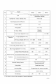


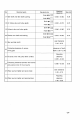


5 Matched clearances
and
wear limit of main parts
No
Matched parts
Standard size
Matched
Wear
limit
clearance
Crankshaft
main journal neck
and main
Shaft
<1>750_00019
1
0.070
-0.
154
0.30
bearing
Hole
<1>75
:~:~~~
2 Crankshaftr thrust ring and crankshaft
0.08-0.23
0.50
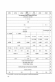
Crankshaft
& connecting
rod
journal neck
Shaft
<1>650_0.019
3
O.
050
-
O.
112
0.30
and
connecting bearing
Hole
<1>65
:~:~~
Shaft
<1>38
=~:
~~
axile clearance
4
Connecting rod big end and crankshaft
0.70
Hole
<1>38
0
+
0
.
10
0.17
-0.43
Piston skirt and cylinder liner
Shaft
<1>95
=~:
~:
5
0.160
-0.225
0.50
Hole
<1>950+0.035
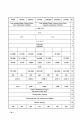
6 Piston pin and connecting
rod
bushing
Shaft
<1>350_0.011
0.009 - 0.045
0.15
Hole
<1>35
:~::
The first compression ring and ring grave
Shaft
<1>3
0
_
0
.
012
7
0.050
- 0.087
0.40
Hole
<1>3
:~:~~~
the second compression ring
and
Shaft
<1>30_0.012
8
0.030-0.062
0.30
ring grave
Hole
<1>3
:~:~~~
oil
ring and ring grave
Shaft
<Jl60_0.012
9
0.030 - 0.062
0.25
Hole
<1>6
:~:
~;~
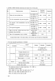
10
Gap
of first compression ring
in
cylinder
Gauge
within<l>95.
00.
0.20-0.40
3.00
11
Gap
of the second & third compression
Gauge
within<l>95.
00
0.15
-0.35
3.00
ring
in
cylinder
12
Gap
of
oill compression ring
in
cylinder
Gauge
within<l>95.
00
0.15
-0.35
3.00
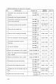
Camshaft journal neck and bushing
Shaft
<1>50
=~:~~~
13
0.080
-0.130
0.25
Hole
<1>50
0
+
0
.
025
Camshaft thrust plate and camshaft
Shaft
<1>12
=~:~;~
14
0.050 - 0.220
0.40
Hole
<1>12
0
+
0
.
100
Cylinder liner over the cylinder block sur-
Shaft
~100+0.050
( selective fitted)
15
face
Hole
~100_0.050
0.030 - 0.080
Shaft
~16
=~:~~
16
Valve push rod
and
push rod hole
0.016
-0.052
0.20
Holet
~160+o.018
~
28 •