Service Manual for WD10 Mechanical Pump Series Engine x Service Manual for WD10 Diesel Engine
Service Manual for WD10 Diesel Engine WD10 China II series diesel engine (China II emission standard)
Service Manual for WD10 Diesel Engine Special Tips Operators must carefully read Diesel Engine Instruction Manual before operating, all technical operations and maintenance regulations specified in the manual must be strictly complied with. Turbocharger rotor is precision high-speed rotating component, unauthorized disassembling and crashing is strictly prohibited, otherwise the “three guarantees” we committed shall automatically become invalid.
Service Manual for WD10 Diesel Engine Preface As an advanced high-speed diesel engine, WD10 is a newly-developed product of Weichai Power Company Limited based on bran-new design concept, which meets China II emission standard. WD10 diesel engine has the features of compact structure, reliable service, excellent dynamic property and economic efficiency, rapid start, easy operation and convenient maintenance. WD10 can achieve advanced emissions target, definitely an ideal engine for heavy vehicles.
Service Manual for WD10 Diesel Engine CONTENTS 1 Usage Instructions for Diesel Engine ..................................................................... 1 11 External View of Diesel Engine ............................................................................. 1 12 Diesel Engine Model Composition and Significance ............................................. 3 13 Diesel Engine Main Technical Parameters ............................................................. 3 14 Unseal of Diesel engine .....
Service Manual for WD10 Diesel Engine 3 Diagnosis and Troubleshooting of Diesel Engine Common Faults ..................... 21 31 Diagnostic Methods .............................................................................................. 21 32 Fault Causes and Elimination Methods ................................................................ 22 321 Diesel Engine Couldn’t Be Started .............................................................. 22 322 Diesel Engine Stops Soon after Starting .........
Service Manual for WD10 Diesel Engine 422 Disassembly, Inspection, Maintenance and Assembly of Cylinder Cover Shield ............................................................................................................ 38 423 Disassembly, Inspection, Maintenance and Assembly of Water Outlet Pipe …………………………………………………………………………...39 424 Disassembly, Inspection, Maintenance and Assembly of Oil-Gas Separator …………………………………………………………………………...
Service Manual for WD10 Diesel Engine 453 Disassembly, Inspection, Maintenance and Assembly of Rocker and Rocker Shaft .............................................................................................................. 79 454 Disassembly, Inspection, Maintenance and Assembly of Valve Tappet and Pushrod ......................................................................................................... 82 455 Disassembly, Inspection, Maintenance and Assembly of Valve .................
Service Manual for WD10 Diesel Engine 497 Disassembly, Inspection, Maintenance and Assembly of Main Oil Gallery Pressure Limiting Valve ............................................................................. 111 498 Disassembly, Inspection, Maintenance and Assembly of Engine Oil Cooler Bypass Valve .............................................................................................. 112 499 Disassembly, Inspection, Maintenance and Assembly of Engine Oil Strainer ………………………………………………………………………….
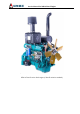
Service Manual for WD10 Diesel Engine 1 Usage Instructions for Diesel Engine 11 External View of Diesel Engine 1
Service Manual for WD10 Diesel Engine 2
Service Manual for WD10 Diesel Engine 12 Diesel Engine Model Composition and Significance WD10 G XXX E2 XX Variant code Emission standard Power code Application code Product series code 13 Diesel Engine Main Technical Parameters Table 1-1 Main Technical Parameters of WD10 China II series diesel engine Engine type Water-cooling, 4-stroke, brake with build-in air bleeding valve, in-line, direct injection, supercharged and intercooling Cylinder diameter/Stroke 126/130 Displacement (L) 9.
Service Manual for WD10 Diesel Engine Cooling mode Water-cooling forced circulation Engine oil pressure (kPa) 350~550 Engine oil pressure at engine idle speed (kPa) 100~250 Allowed longitudinal Front/Rear inclination (°) Long-term 10/10 Short-term 30/30 Long-term 45/15 Short-term 45/30 Allowed transverse inclination (°) Exhaust pipe side/Injection pump side Crankshaft rotating direction (View from free end) Clockwise Table 1-2 Main Technical Parameters of WD10 China II series diesel engine Un
Service Manual for WD10 Diesel Engine Minimum fuel consumption under full load g/(kWh) 196 Cold start—with aid o -25 White smoke discharge Light After 20s idling≤15% obscuration Noise at 1m dB(A) <104 B10 service life km 800,000 C 14 Unseal of Diesel engine After opened the engine packing container, the user should firstly check the engine and its accessories according to the packing list, check whether engine appearance is damaged and whether connections are loose, and then perform the follo
Service Manual for WD10 Diesel Engine 15 Lifting of Diesel Engine Keep the center line of engine crankshaft horizontal during lifting, tilting or unilateral lifting is strictly forbidden. Keep the lifting-up and putting-down process slowly (refer to Fig. 1-1). Correct Wrong Fig. 1-1 Lifting of diesel engine 16 Installation of Engine For installation, please ensure the center line of engine crankshaft and input shaft axis of transmission (transmission box, gearbox or generator) are coaxial.
Service Manual for WD10 Diesel Engine on instrument panel or check the fuel tank. (3) Check engine oil level Engine oil level should between the bottom scale and top scale on oil dipstick, add engine oil through oil filling port if necessary. (4) Check whether all accessories are reliably connected to the engine and eliminate abnormal phenomenon. Check whether start-up system wirings are normal, whether storage battery is fully charged.
Service Manual for WD10 Diesel Engine (5) Parameters and check points that should always be noticed during normal use: Engine oil pressure (main gallery) 350~500kPa. Engine oil temperature in oil sump <110oC. Coolant outlet temperature 80+5oC, should not exceed 93oC Turbine-rear exhaust temperature ≤550oC; Intake air temperature after intercooler 50~55oC.
Service Manual for WD10 Diesel Engine 2 Maintenance Guidelines for Diesel Engine 21 Fuel Oil, Engine oil, Coolant and Auxiliary Materials 211 Fuel Oil Summer: 0# diesel fuel (GB252) Winter: -10# diesel fuel is generally used, choose -20# diesel fuel if ambient temperature lower than -15oC, and choose -35# diesel fuel if ambient temperature lower than -30oC. The chosen fuel should meet requirements in appendix C.6 of GB17691-2005 (Revised in June 2008).
Service Manual for WD10 Diesel Engine 213 Lubrication of Tensioning Wheel Apply general purpose lithium lubricating grease for lubrication of tensioning wheel (refer to GB/T5671-1995) 214 Antifreeze Additive in Engine Cooling System The adopted antifreeze additive is ethylene glycol, and it is allowed to replace it with domestic long-acting antifreeze additive with reliable quality, refer to related description for specific application method.
Service Manual for WD10 Diesel Engine We can get that required antifreeze additive for -20oC is 13.5L Difference value between -30oC and -20oC is 4L For the difference value 4L, another 50% of that is required and necessary, because of before adding antifreeze additive, a part of coolant must be drained out, and antifreeze additive in this part of coolant will be drained out too. So required antifreeze additive is: 4L+50%*4L=6L.
Service Manual for WD10 Diesel Engine Used for the seal Loctite 277 between core and Other bowl type plugs hole Used to seal top end Loctite 270 face of cylinder Pushrod bush-Cylinder cover cover Fitting surface between cylinder block and crankcase, fitting surface between engine block and engine front cover Rear end face and flywheel connecting board Fitting surface between engine oil filter seat and Loctite 518 (Renewed Apply on shining crankcase product of metallic surface for Water pump rear cover-engin
Service Manual for WD10 Diesel Engine Expansion water tank Fig. 2-3 Expansion water tank 222 Check Engine Oil Level Check whether engine oil level is between the bottom scale and top scale on oil dipstick. Under no circumstances should the engine be started if the oil level is lower than the bottom scale (L) or higher than the top scale (H). Oil level checking should be done at least 5min later after engine stopped, in order to let engine oil have enough time to return to oil sump.
Service Manual for WD10 Diesel Engine 223 Check Fuel Level Check fuel level gauge on instrument panel and add fuel timely. 224 Check “Three Leakages” Check engine appearance for water leakage, air leakage and oil leakage. 225 Check Fan Visually check whether fan blades are damaged, and whether connecting bolts are tightened. Fig. 2-5 Check fan 226 Check Belt The belt is automatically taken-up by a tightening wheel, user can check the tension of the belt by pressing it with hand.
Service Manual for WD10 Diesel Engine 228 Check Whether Running Sound is Normal 229 Check Whether Rotating Speed and Vibration are Normal 23 Periodic Maintenance Replace engine oil Screw off oil drain plug on the bottom of oil sump to drain all engine oil out and then screw on the plug, refer to Fig. 2-8. Open the filler cap (refer to Fig. 2-7), add engine oil through filling port, observe oil dipstick until oil level meets the requirements, install the filler cap.
Service Manual for WD10 Diesel Engine intake valve (and exhaust valve) and rocker). (3) Measure the clearance between rocker and valve rod upper surface with feeler gauge. Required intake valve clearance for WD10 diesel engine is 0.3mm; while that for exhaust valve is 0.4mm. If the clearance is too large or too small, you can rotate the adjusting screw to adjust until the clearance meets the requirements. Refer to Fig. 2-9. Adjusting screw Cold-state intake valve clearance is 0.
Service Manual for WD10 Diesel Engine ATTENTION: In the adjusting process, you should rotate the bolt assembly 2 until the feeler gauge is gently infibulated, so that valve rocker piston 5 can be pushed to the bottom and no clearance between piston and piston hole bottom. 11 Hexagon bolt 12 Supporting arm 1 Adjusting nut 2 Bolt 3 Valve-rocker assembly 4 Steel ball 10 Pushrod end 5 Valve-rocker piston 6 Piston spring 7 Roller pin 9 Rocker seat 8 Ball valve spring Fig.
Service Manual for WD10 Diesel Engine Fig. 2-11 Deflating of coarse filter Drain water in water collector: ATTENTION: When water collector is full or spinning coarse filter is replaced, it is required to drain the water in water collector out. Draining steps (as shown in Fig. 2-12): Open the oil drain plug 2 on bottom of water collector1 to drain all water out. Retighten the plug. Fig. 2-12 Drain water in water collector Replace water collector: Replacing steps (as shown in Fig.
Service Manual for WD10 Diesel Engine Install the screw with hand and tighten it with tool. If the collector needs to be used on a new spinning filter, check it for damage first. Install the collector with torque wrench, tightening torque is 20Nm. Fig. 2-13 Replace water collector Check intake system Check whether intake rubber hose is aged and cracked, whether the circumferential band is loose.
Service Manual for WD10 Diesel Engine infiltration of dust and impurities will lead to premature wear of engine. Remove the filter element from air filter, pat its end faces gently to clean the dust on it, blow it with compressed air reversely (from inside to outside) is also feasible. Fig. 2-15 Air filter element ATTENTION: Do not let the air broke filter paper and do not clean filter paper with water or oil, do not pat or strike the filter element fiercely.
Service Manual for WD10 Diesel Engine 3 Diagnosis and Troubleshooting of Diesel Engine Common Faults WD10 China II series diesel engine is designed and manufactured under strict quality guarantee system, each delivered engine has passed specified tests. Since diesel engine is precision machinery, guarantee for long-term reliable service is inseparable from correct maintenance.
Service Manual for WD10 Diesel Engine ATTENTION: 1. Diesel engine fault cause determination is an extremely careful job. Before basically be sure about the cause, it’s not allowed to disassemble the engine casually, otherwise instead of eliminating the fault, some severe trouble may occur due to improper reassembling. 2.
Service Manual for WD10 Diesel Engine 322 Diesel Engine Stops Soon after Starting 1. Blockage of fuel filter Disassemble the filter body to clear up the water and dirt, replace the filter element if necessary. 2. Air in fuel system Expel the air and check airtightness of joints, check whether the air bleed screw is tightened. 3. Fuel delivery pump doesn’t work Check fuel delivery pump piston and valves, clean and repair. 4. Inferior fuel, high water content Clean fuel filter and replace the fuel.
Service Manual for WD10 Diesel Engine 12. Incorrect valve or injection timing Check and adjust it. 13. Governor high-speed performance is poor Check the speed control characteristic and adjust. regulating 14. High engine oil level in oil sump 15. Air leakage in cylinder gasket Check oil dipstick and drain redundant engine oil out. Check the compression pressure when engine is running, replace damaged gasket. 16.
Service Manual for WD10 Diesel Engine 325 Engine Gives off Black Smoke 1. Blockage of intake pipe or high exhaust Clean it up. back pressure 2. Inferior fuel Clean and replace. 3. Incorrect valve or injection timing Adjust valve clearance and fuel supply advance angle according related requirements. 4. Bad atomization Check and repair or replace. 5. Overmuch fuel pumped by the injection Check and adjust (should be performed by pump professional personnel). 6.
Service Manual for WD10 Diesel Engine 327 Turbocharger Intake Port and Intake Pipe Are Accumulated with Engine Oil 1. Turbocharger sealing failure Repair or replace the turbocharger. 2. Oil-gas separator failure Replace. 3. High engine oil level in oil sump Check oil dipstick and drain redundant engine oil out. 328 Unstable Engine Speed 1. Inferior fuel, high water or wax content Replace the fuel. 2.
Service Manual for WD10 Diesel Engine 7. Large filtering resistance of engine oil Replace filter element. filter 8. Blockage of engine oil cooler Check and clean. 9. Blockage of main oil gallery Check and clean. 10. Large bearing shell damaged bearing shell clearance, or Check and replace. 11. Severe wear of parts, overhaul needs to Check working hour of engine, overhaul the engine. be done 3210 High Cooling Water Temperature 1.
Service Manual for WD10 Diesel Engine 9. Severe wear of parts, overhaul needs to Check working hour of engine, overhaul the engine. be done 10. Crankshaft and the follower main shaft Check the installing support, repair. are not concentric 11. The applied engine oil quality fails to Choose specified engine oil brand. meet the requirements 3212 Excessive Noise 1. Inferior fuel Replace the fuel. 2. Too low cooling water temperature Check the thermostat and replace it if necessary. 3.
Service Manual for WD10 Diesel Engine 3214 Underpowered Starter Motor 1. Undercharged battery Check, recharge or replace the battery. 2. Bearing sleeve wear Replace the assembly. 3. Bad contact of electric brush Clean the brush or replace it. 4. Dirty or burnt commutator Wipe out oil dirt and polish it with abrasive paper or replace it. 5. Loose weld of terminals Re-weld. 6. Bad contact of switch Check the switch and replace it. 7.
Service Manual for WD10 Diesel Engine 3217 Unstable Charging Voltage 1. Rotor coil or stator coil is about to in Repair or replace. open circuit or short circuit 2. Bad contact of electric brush Repair. 3. Loose terminals, bad contact Repair. 4. Damaged voltage regulator Repair. 5. Improperly adjusted voltage Check and adjust. 3218 Generator Overcharging 1. Short circuit in battery Repair or replace. 2. Too high regulator adjusting voltage Repair and adjust. 3.
Service Manual for WD10 Diesel Engine 4 Disassembly & Assembly of Diesel Engine 41 Overview Please comply with instructions in this manual strictly to disassemble and assemble the engine and pay special attention to operations which danger signs and safety signs are involved in this manual, in order to ensure personal safety and avoid accidents. 411 Danger Signs This sign is world-recognized danger sign. In this manual, this sign is used to emphasize the importance of following information.
Service Manual for WD10 Diesel Engine Safety information described in this manual cannot cover all safety precautions, if the procedures or actions that are not recommended in this manual are used, you must ensure the safety of the operator and machine.
Service Manual for WD10 Diesel Engine 413 Recommended Tools Signs Information 2.5mm hexagon wrench 5mm hexagon wrench 8mm socket Slotted screw driver Dedicated tool 10mm slotted hexagon wrench If the methods or tools that are not recommended in this manual are used, you must ensure safety to avoid life risk to yourself or other people, in the meantime make sure the operating, maintenance and repair methods wouldn’t bring damage to the engine or potential safety hazard.
Service Manual for WD10 Diesel Engine (10) Be sure to seek for medical help immediately if any adverse reaction happened to your skin. (11) If possible, clear away oil dirt on parts before transporting the engine. (12) Please wear google or protective mask if there is risk of damaging your eyes. Eye washing fluid must be prepared within reach. (13) When maintaining the engine, prevent oil or other liquid spilling on the ground.
Service Manual for WD10 Diesel Engine 417 Explode View of the Whole Engine Turbocharger Cylinder cover shield Cylinder cover Oil-gas separator Exhaust pipe Cylin der sl eeve Water outlet pipe Thermostat Intake pipe Cylinder Block Pushrod Valve Engine oil cooler cap Tappet Camshaft Engine oil filter Flywheel housing Oil Piston dipstick Generator Engine oil cooler A/C compressor Air compressor Injector Flywheel Crankshaft Belt Connecting rod High pressure fuel pipe Damper Engine oil pump St
Service Manual for WD10 Diesel Engine 42 Cylinder Cover Assembly 421 Disassembly and Assembly of Cylinder Cover Assembly 4211 Exploded View of Cylinder Cover Assembly Cylinder cover is located on top of cylinder block, combustion chamber is jointly formed by cylinder cover and piston head. Parts that connected with cylinder cover are intake pipe, exhaust pipe, water outlet pipe, EVB oil pipe, injector, cylinder cover shield, oil-gas separator, cylinder cover gaskets and parts of valve mechanism.
Service Manual for WD10 Diesel Engine (6) Disconnect EVB oil pipe and pipe joint; (7) Disconnect injector wiring harness, remove injector oil return pipe and high pressure fuel pipe, refer to disassembly of fuel system for details; (8) Remove the injector, refer to disassembly of fuel system for details; (9) Remove cylinder cover shields and its gaskets; (10) Remove rocker assembly and pushrod, refer to disassembly of valve mechanism for details; (11) Remove cylinder cover assembly, and take down the gasket
Service Manual for WD10 Diesel Engine 422 Disassembly, Inspection, Maintenance and Assembly of Cylinder Cover Shield 4221 Exploded View of Cylinder Cover Shield Cylinder cover shield bolt Cylinder cover shield Cylinder cover shield gasket Fig. 4-3 Exploded view of cylinder cover shield 4222 Steps to Disassemble Cylinder Cover Shield (1) Screw off cylinder cover shield bolts orderly; (2) Pull the shield vertically up to take it and its gaskets down. As shown in Fig. 4-3.
Service Manual for WD10 Diesel Engine Check whether there is manufacturing defect, usage defect or damage on cylinder cover shield gaskets and cylinder cover before assembling. (2) Clean up cylinder cover upper surface and assemble cylinder cover shield gaskets orderly. (3) Clean up cylinder cover shields and install them on cylinder cover orderly. (4) Install cylinder cover shield bolts and tighten them.
Service Manual for WD10 Diesel Engine 4233 Inspection and Maintenance of Water Pipe (1) Check whether there is water leakage trace on the pipe before disassembling; check the pipe for damage like crack and corrosion, a cracked pipe should be replaced, for corrosion that may affect reliability of the pipe, the cause should be analyzed and corroded pipe should be replaced.
Service Manual for WD10 Diesel Engine 424 Disassembly, Inspection, Maintenance and Assembly of Oil-Gas Separator 4241 Exploded View of Oil-Gas Separator Front hanger plate Fixing bolt Oil-gas separator outlet pipe Oil-gas separator Flange and gasket Clamp Oil-gas separator oil return pipe Bolt Clamp and bolt Clamp Oil-gas separator intake pipe joint Connecting pipe Fig.
Service Manual for WD10 Diesel Engine 4244 Steps to Assemble Oil-Gas Separator Assembling steps are contrary to disassembling ones. Do not mix up the rubber hoses and hoses joints (refer to Fig. 4-5), connect each hose to the engine properly. 425 Disassembly, Inspection, Maintenance and Assembly of Hanger Plates 4251 Exploded View of Hanger Plates Hexagon bolt Rear hanger plate Hexagon bolt Front hanger plate Fig.
Service Manual for WD10 Diesel Engine 4254 Steps to Assemble Hanger Plates Firstly distinguish the front hanger plate and rear hanger plate, front hanger plate should be installed on front end of engine (fan end), and rear hanger plate should be installed on rear end of engine (flywheel end), fasten the plates with M12 hexagon bolts (as shown in Fig. 4-6), required tightening torque is 100~125Nm.
Service Manual for WD10 Diesel Engine details). Besides, for engine with EVB oil pipe, the pipe need to be remove too.
Service Manual for WD10 Diesel Engine Fig. 4-8 Depth micrometer Refer to Table 4-1 for valve recession requirements. If valve recession exceeds allowed range, check wear condition of valve and valve seat, replace the valve with a new one to determine wear condition of valve seat by measuring the valve recession again, if the valve recession still exceeds allowed range, the cylinder cover must be replaced to ensure reliability of diesel engine.
Service Manual for WD10 Diesel Engine (7) Check the disassembled cylinder cover gaskets for visible damage and analyze the cause, cylinder cover gaskets are disposable, and should be replaced once removed. (8) Check whether valve rod seal cartridge rubber lip is damaged, whether the spring is in failure and whether there is other abnormal phenomenon before disassembling, seal cartridge should be replaced once removed. 4264 Steps to Assemble Cylinder Cover (1) Install cylinder cover auxiliary bolts Fig.
Service Manual for WD10 Diesel Engine 2) Rub-up cylinder sleeve inner wall and apply clean engine oil on the wall; Clean up upper surface of cylinder block, and place cylinder gaskets correctly by aligning the holes; 3) Check and make sure the holes on cylinder cover gasket are correctly aligned to holes on cylinder block. (3) Install valve rod seal cartridges Spring Fig.
Service Manual for WD10 Diesel Engine 2) Check and make sure cylinder cover air passage and water passage are free of foreign matter; Check and make sure the cylinder is free of foreign matter, cylinder cover gasket and cylinder cover undersurface are clean; 3) Apply pin-plane mode to locate the cylinder cover before fastening cylinder cover bolts; 4) Assemble cylinder cover.
Service Manual for WD10 Diesel Engine 6) Tighten cylinder cover main bolts with torque wrench orderly to 200Nm and mark the bolts; 7) Tighten each cylinder cover auxiliary nut for further 90°with torque wrench orderly and mark the new position of the nuts; 8) Tighten each cylinder cover main bolt for further 90°with torque wrench orderly and mark the new position of the bolts; 9) Tighten each cylinder cover auxiliary nut for another 90°with torque wrench orderly and the tightening torque should reach 120~16
Service Manual for WD10 Diesel Engine Fig. 4-17 Assembly of cylinder cover main bolts Fan side Flywheel side Fig.
Service Manual for WD10 Diesel Engine 43 Engine Block Assembly 431 Disassembly, Inspection, Maintenance and Assembly of Engine Block Assembly 4311 Exploded View of Engine Block Assembly Cylinder cover auxiliary bolt Cylinder sleeve Engine block module Elastic cylindrical pin Pre-glued set screw Cylindrical pin Bowl shape plug Rivet Bowl shape plug Self-locking gasket Hexagon socket head cap screw Hexagon bolt Fig.
Service Manual for WD10 Diesel Engine Compound gasket Main oil gallery rear plug Bowl shape plug Rivet Seal ring Main bearing bolt Fig. 4-20 Exploded view of engine block assembly 4312 Steps to Disassemble Engine Block Assembly (1) Remove crankcase fastening bolts (key point 1); (2) Remove main bearing bolts (key point 2); (3) Remove seal rings; (4) Remove cylinder cover auxiliary bolts (key point 3); (5) Remove main oil gallery plug; (6) Remove cylinder sleeve (key point 4).
Service Manual for WD10 Diesel Engine Key point 2: Assembling: Apply clean lubricating oil on crankcase bearing surface and thread of main bearing bolts, and then tighten them according to following order: Tightening torque 265±25Nm Key point 3: Assembling: Tighten cylinder cover auxiliary bolts according to the following order, cylinder cover auxiliary bolts are allowed to use twice at most.
Service Manual for WD10 Diesel Engine 432 Disassembly, Inspection, Maintenance and Assembly of Engine Block Module 4321 Exploded View of Engine Block Module Bowl shape plug Cylinder block Bowl shape plug Camshaft sleeve Crankcase Oil dipstick pipe head Oil dipstick Oil dipstick pipe Cylindrical pin with internal thread Bowl shape plug Bowl shape plug Crankshaft sleeve Oil dipstick pipe Oil dipstick pipe sleeve Fig.
Service Manual for WD10 Diesel Engine 4322 Steps to Disassemble Engine Block Module (1) Remove cylindrical pins (with internal thread); (2) Remove camshaft sleeve (key pint 1); (3) Remove main bearing bolts and crankcase fastening bolts (refer to 431); (4) Remove crankcase (key point 2); (5) Remove oil dipstick assembly (key point 3) 4323 Inspection and Maintenance of Engine Block Module Key point 1: Disassembling: Remove camshaft sleeve with dedicated tools and protect other sleeves in this process.
Service Manual for WD10 Diesel Engine 433 Disassembly, Inspection, Maintenance and Assembly of Engine Front Cover 4331 Exploded View of Engine Front Cover Engine front cover Hexagon flange toothed bolt Seal ring Fig.
Service Manual for WD10 Diesel Engine 4334 Steps to Assemble Engine Front Cover Assembling steps are contrary to disassembling ones. 434 Disassembly, Inspection, Maintenance and Assembly of Gear Housing 4341 Exploded View of Gear Housing Timing gear housing Seal ring O-shape seal ring Hexagon flange bearing surface toothed bolt Hexagon plug Compound gasket Cylindrical pin Fig.
Service Manual for WD10 Diesel Engine 4343 Inspection and Maintenance of Gear Housing Key point 1: Assembling: Tighten gear housing fastening bolts according to the following order crosswise. Tightening torque 44~58Nm Fig. 4-24 Key point 2: Assembling: Check whether seal ring is damaged, replace it if so. When assembling, seal ring should be applied with oil and fully pressed into seal groove, protect the ring in this process.
Service Manual for WD10 Diesel Engine 435 Disassembly, Inspection, Maintenance and Assembly of Flywheel Housing 4351 Exploded View of Flywheel Housing Stud Spring washer 1-type hexagon bolt Flywheel housing Flywheel housing bolt Monitoring window cap Hexagon bolt Cylindrical pin Fig.
Service Manual for WD10 Diesel Engine Fig. 4-26 Key point 2: Assembling: Apply sealant on fitting surfaces of flywheel housing and engine block, pay attention not to crash flywheel housing during lifting. 4354 Steps to Assemble Flywheel Housing Assembling steps are contrary to disassembling ones.
Service Manual for WD10 Diesel Engine 4362 Steps to Disassemble Oil Sump (1) Turn over the engine to keep oil sump upward (key point 1); (2) Remove oil sump fastening bolts (key point 2); (3) Remove oil sump support blocks; (4) Take down oil sump and the seal ring; (5) Remove the compound gasket and magnetic screw plug assembly. 4363 Inspection and Maintenance of Oil Sump Key point 1: Disassembling: Before the disassembling, all engine oil should be drained out.
Service Manual for WD10 Diesel Engine 437 Disassembly, Inspection, Maintenance and Assembly of Piston Nozzle 4371 Exploded View of Piston Nozzle Hollow bolt Seal gasket Nozzle assembly Elastic cylindrical pin Fig. 4-29 Exploded view of piston nozzle 4372 Steps to Disassemble Piston Nozzle (1) Remove the hollow bolt (key point 1); (2) Remove nozzle assembly; (3) Remove elastic cylindrical pin (key point 2).
Service Manual for WD10 Diesel Engine 4374 Steps to Assemble Piston Nozzle Assembling steps are contrary to disassembling ones. 438 Disassembly, Inspection, Maintenance and Assembly of Thrust Plates 4381 Exploded View of Thrust Plates Upper thrust plate Lower thrust plate Fig. 4-30 Exploded view of thrust plates 4382 Steps to Disassemble Thrust Plates (1) Remove crankcase (refer to section 432); (2) Remove crankshaft (refer to section 444); (3) Remove thrust plates (key point 1).
Service Manual for WD10 Diesel Engine side with oil groove should be outward. 4384 Steps to Assemble Thrust Plates (1) Install crankshaft; (2) Install upper thrust plates (without lug); (3) Install lower thrust plates (key point 1). 439 Disassembly, Inspection, Maintenance and Assembly of Front and Rear Oil Seals 4391 Exploded View of Front and Rear Oil Seals Front oil seal Rear oil seal Fig.
Service Manual for WD10 Diesel Engine tool. Disassembling: Removed oil seals should not be reused. 4394 Steps to Assemble Front and Rear Oil Seals (1) Install crankcase; (2) Install rear oil seal; (3) Install gear housing; (4) Install front oil seal.
Service Manual for WD10 Diesel Engine 44 Crank-Rod Mechanism 441 Disassembly and Assembly of Crank-Rod Mechanism 4411 Exploded View of Crank-Rod Mechanism Main bearing bolt Main bearing shell Crankcase Crankshaft Connecting rod big end cap Flywheel ring gear Crankshaft timing gear Damper Flywheel Pulley Flywheel bolt Bearing Flange Flywheel housing Pulley bolt Engine block Piston-rod assembly Fig.
Service Manual for WD10 Diesel Engine 442 Disassembly, Inspection, Maintenance and Assembly of Piston-Rod Assembly 4421 Exploded View of Piston-Rod Assembly Crankshaft Piston-rod assembly Fig. 4-33 Schematic diagram of piston-rod assembly First compression ring Second compression ring Piston pin Oil ring Piston Piston pin circlip Connecting rod body Connecting rod cap Connecting rod bearing shell Connecting rod bolt Fig.
Service Manual for WD10 Diesel Engine 4422 Steps to Disassemble Piston-Rod Assembly (1) Remove circlip on two sides of piston with internal circlip plier and push piston pin out, take down the connecting rod body. Number the piston pins, connecting rod bodies and place them orderly. (2) Remove first compression ring, second compression ring and oil ring with piston ring plier and mark them.
Service Manual for WD10 Diesel Engine (5) Adjust opening direction of each ring: The opening direction of first compression ring should be 30°to piston pin center line, opening direction of the second compression ring should be 120° to that of the first compression ring, and opening direction of oil ring should be 120°to both that of first compression ring and second compression ring, also should be perpendicular to piston pin center line. As shown in Fig. 4-35.
Service Manual for WD10 Diesel Engine 443 Disassembly, Inspection, Maintenance and Assembly of Crankshaft 4431 Exploded View of Crankshaft Main bearing bolt Crankcase Crankshaft Flywheel ring gear Flywheel Main bearing shell Bearing Crankshaft timing gear Damper Baffle ring Pulley Flywheel bolt Flange Engine block Pulley bolt Fig.
Service Manual for WD10 Diesel Engine (6) Check wear condition of crankshaft journal, check bend and distortion condition of crankshaft. 4434 Steps to Assemble Crankshaft (1) Clean up cylinder bottom holes. (2) Press main bearing upper shells into cylinder bottom holes and clean up scraped foreign matter. a) The bearing shells should be strictly inspected for bump damage before assembling, and shell with bump damage should not be reused even if repaired.
Service Manual for WD10 Diesel Engine (11) Firstly pre-tighten each bolt with low-torque pneumatic impact wrench, and then tighten each bolt to 80Nm orderly, thirdly the torque should reach 250~280Nm. Assembly of crank shaft is finished. 444 Disassembly, Inspection, Maintenance and Assembly of Flywheel and Ring Gear 4441 Exploded View of Flywheel and Ring Gear Flywheel Flywheel ring gear Hexagon bolt Bearing Crankshaft Flywheel bolt Baffle ring Stud Locating pin Fig.
Service Manual for WD10 Diesel Engine 4444 Steps to Assemble Flywheel and Ring Gear (1) Fix the flywheel ring gear on flywheel with bolts; (2) Knock the pin into crankshaft rear end fully. (3) After inserting flywheel guide rod into crankshaft threaded hole, install flywheel and pre-tighten the bolts diagonally. a) Apply lubricating oil on flywheel bolt thread and bearing surfaces. b) Flywheel bolt M14×1.
Service Manual for WD10 Diesel Engine 445 Disassembly, Inspection, Maintenance and Assembly of Damper and Crankshaft Pulley 4451 Exploded View of Damper and Crankshaft Pulley Crankshaft timing gear Flange Crankshaft Damper Crankshaft pulley Pulley bolt Fig. 4-39 Exploded view of damper and crankshaft pulley 4452 Steps to Disassemble Damper and Crankshaft Pulley Screw off pulley bolts and then take down pulley and damper orderly.
Service Manual for WD10 Diesel Engine 446 Disassembly, Inspection, Maintenance and Assembly of Crankshaft Bearing Shell 4461 Exploded View of Crankshaft Bearing Shell Main bearing upper shell Crankshaft Main bearing lower shell Fig. 4-40 Exploded view of crankshaft bearing shell 4462 Steps to Disassemble Crankshaft Bearing Shell Push the shells out with hand, and mark the removed shells (should be corresponded with fitting holes on engine block and crankcase).
Service Manual for WD10 Diesel Engine 45 Valve Mechanism 451 Disassembly and Assembly of Valve Mechanism 4511 Exploded View of Valve Mechanism Adjusting nut Hexagon screw Supporting arm Adjusting bolt assembly Adjusting nut Rocker shaft Intake rocker Adjusting screw Valve lock clamp Upper valve spring seat Valve inner spring Valve outer spring Lower valve spring seat Valve Camshaft Exhaust rocker Adjusting screw Valve cap Pushrod Locating pin Camshaft timing gear Tappet Bowl shape plug Hexagon bolt H
Service Manual for WD10 Diesel Engine (3) Install valve tappet and pushrod, refer to assembly of valve tappet and pushrod for details; (4) Assemble intake and exhaust valves, refer to assembly of valves for details; (5) Install rocker and rocker shaft, refer to assembly of rocker and rocker shaft for details; 452 Disassembly, Inspection, Maintenance and Assembly of Camshaft 4521 Exploded View of Camshaft Camshaft Thrust plate Camshaft bearingshell Camshaft timing gear Locating pin Hexagon screw Hexagon bo
Service Manual for WD10 Diesel Engine abrasion. (2) Measure camshaft main journal circular run-out. Maximum allowed Measured value circular run-out Camshaft The second main journal (Between cylinder 1 and cylinder 2) 0.04 The third main journal (Between cylinder 2 and cylinder 3) 0.05 The fourth main journal (Between cylinder 3 and cylinder 4) 0.06 The fifth main journal (Between cylinder 4 and cylinder 5) 0.05 The sixth main journal (Between cylinder 5 and cylinder 6) 0.
Service Manual for WD10 Diesel Engine (5) Turn the engine anticlockwise (view from timing gear housing end) until cylinder 1 and 6 reach TDC. At this point, piston upper end should be aligned to cylinder block upper surface. (6) Draw a straight line across flywheel housing and flywheel, install the dial and adjust it until 0° position is aligned to the “half line” on flywheel housing, install timing gear. (7) The mark on timing gear should be aligned to “OT” mark on timing gear housing.
Service Manual for WD10 Diesel Engine 4532 Steps to Disassemble Rocker and Rocker Shaft (1) Rotate crankshaft to check whether rocker is flexible. (2) Measure each valve clearance, and check the change of valve clearance. (3) If the rocker is not flexible or too big valve clearance, loosen hexagon nut and then take down the supporting arm, rocker shaft, intake and exhaust rocker assembly, mark them to prevent confusion.
Service Manual for WD10 Diesel Engine valve clearance: As shown in Fig. 4-44, firstly loose the adjusting bolt 2, and then adjust valve clearance adjusting screw on pushrod end 10 without compressing exhaust valve rocker sealing surface until total valve clearance is 0.4mm, and then tighten adjusting nut.
Service Manual for WD10 Diesel Engine 3) Rotate the engine for 360°, so that cylinder 6 can be in compression TDC, adjust intake valve clearance of No. 6, 5, 3 cylinder and exhaust valve clearance of No. 6, 4, 2 cylinder, and EVB valve clearance. 4) Check valve timing of cylinder 1 in cold state, intake valve TDC 18°~23°, exhaust valve TDC 20°~25°.
Service Manual for WD10 Diesel Engine (4) Check whether pushrod two ends are worn; (5) Check whether valve tappet surface and undersurface are worn; (6) Check whether valve tappet inner socket head is worn. 4544 Steps to Assemble Valve Tappet and Pushrod (1) Check valve tappets and pushrods, replace them if necessary.
Service Manual for WD10 Diesel Engine 4552 Steps to Disassemble Valve (1) Depress valve springs with vale spring compressor or valve overhead plier or other tools, take out valve lock clamp, upper valve spring seat and lower valve spring seat and valve springs orderly; (2) Take valve out of valve seat.
Service Manual for WD10 Diesel Engine 456 Disassembly, Inspection, Maintenance and Assembly of Intermediate Gear 4561 Exploded View of Intermediate Gear Sleeve Intermediate gear shaft Gasket Bolt Intermediate gear Fig.
Service Manual for WD10 Diesel Engine 4564 Steps to Assemble Intermediate Gear (1) Install engine oil pump, crankshaft and engine oil pump intermediate gear module orderly; (2) Install gear housing. Before assembling gear housing, put intermediate gear shaft into intermediate gear assembly (intermediate gear and sleeve). For intermediate gear the end with “V” mark should face outward. And then upside-down the engine (to prevent intermediate gear assembly falling off) and install intermediate gear assembly.
Service Manual for WD10 Diesel Engine 46 Intake and Exhaust System 461 Disassembly and Assembly of Intake and Exhaust System 4611 Exploded View of Intake and Exhaust System Intake pipe Turbocharger Exhaust pipe Fig. 4-50 Exploded view of valve intake and exhaust system 4612 Steps to Disassemble Intake and Exhaust System (1) Loosen air filter fixing bolts and hose clamps, take down air filter and hoses.
Service Manual for WD10 Diesel Engine 462 Disassembly, Inspection, Maintenance and Assembly of Intake Pipe 4621 Exploded View of Intake Pipe Nut Stud Intake pipe end cover gasket Intake pipe gasket Intake pipe Intake pipe end cover Intake heater Intake heater gasket Intake pipe bolt Intake pipe adapter Stud Nut Fig.
Service Manual for WD10 Diesel Engine 463 Disassembly, Inspection, Maintenance and Assembly of Exhaust Pipe 4631 Exploded View of Intake Pipe Front exhaust pipe Exhaust pipe seal ring Exhaust pipe bolt Exhaust pipe gasket Rear exhaust pipe Exhaust pipe heat shield bolt Heat shield bolt Heat shield bolt Exhaust pipe heat shield bolt Fig.
Service Manual for WD10 Diesel Engine (2) Exhaust pipe bolts should be applied with molybdenum disulfide, recommended tightening torque for exhaust pipe fixing bolts is 65~80Nm. Exhaust pipe bolts cannot be reused more than twice. 464 Disassembly, Inspection, Maintenance and Assembly of Turbocharger System 4641 Exploded View of Turbocharger System Stud Lock nut 2-type all-metal hexagon nut Turbocharger Stud Turbocharger gasket Fig.
Service Manual for WD10 Diesel Engine Press measuring head of dial indicator against compressor end, push and pull the shaft axially and record value difference of the indicator. As shown in Fig. 4-54. Required range is 0.088~0.118mm, if exceeds this range, then it indicates that thrust bearing plate or thrust plate and bearing is worn, you must find out the cause and eliminate the problem. Fig.
Service Manual for WD10 Diesel Engine (1) Check whether the pipe connection between turbocharger and engine is loose, eliminate the problem in time. (2) Check turbocharger for air leakage and oil leakage, eliminate the fault in time. (3) Check whether turbocharger fastening screws are loose, eliminate the problem timely. (4) Check air filter, clean it timely if there is too much dust accumulated in the filter.
Service Manual for WD10 Diesel Engine 47 Fuel System 471 Disassembly and Assembly of Fuel System 4711 Exploded View of Fuel System Fig. 4-56 Exploded view of fuel system 4712 Steps to Disassemble Fuel System (1) Remove low pressure fuel pipe module; (2) Remove high pressure fuel pipe module; (3) Remove injector module; (4) Remove filter module; (5) Remove high pressure fuel injection pump module. 4713 Steps to Assemble Fuel System Assembling steps are contrary to disassembling ones.
Service Manual for WD10 Diesel Engine 472 Disassembly, Inspection, Maintenance and Assembly of Fuel Injection Pump 4721 Exploded View of Fuel Injection Pump Fig.
Service Manual for WD10 Diesel Engine 4724 Steps to Assemble Fuel Injection Pump (1) Install fuel injection pump flange, apply a small amount of lubricating oil on pump rubber ring; (2) Screw on the hexagon bolts to connect fuel injection pump and the flange; (3) Install injection pump gears, specification of fuel injection pump gear lock nut is M24×1.
Service Manual for WD10 Diesel Engine 473 Disassembly, Inspection, Maintenance and Assembly of High Pressure Fuel Pipes 4731 Exploded View of High Pressure Fuel Pipes Fig.
Service Manual for WD10 Diesel Engine 474 Disassembly, Inspection, Maintenance and Assembly of Fuel Injector 4741 Exploded View of Fuel Injector Fig. 4-60 Exploded view of fuel injector 4742 Steps to Disassemble Fuel Injector (1) Remove the hexagon bolts that used to fix injector pressing block; (2) Remove injector pressing block and fixed block; (3) Take injector assembly out of cylinder cover.
Service Manual for WD10 Diesel Engine (2) All kinds of protective caps only need to be removed before assembling; (3) Place the injector into cylinder cover and tighten injector clamping bolt to 3Nm; (4) Loose injector clamping bolt until axial force posed on injector is 0kN; (5) Pre-tighten high pressure joint to 15~20Nm (nuts); (6) Tighten injector clamping bolt for 10Nm+120°; (7) Tighten high pressure joint to 50~55Nm (nuts); (8) High pressure joint, O-shape seal rings and sealing gaskets are disposal an
Service Manual for WD10 Diesel Engine 48 Cooling System 481 Disassembly and Assembly of Cooling System 4811 Exploded View of Cooling System The function of cooling system is to ensure diesel engine can continuously work at proper temperature. Forced circulation cooling offers the best guarantee to keep the engine in normal operating temperature, which mainly consists of water pump, fan, expansion water tank, water tank and thermostat.
Service Manual for WD10 Diesel Engine (4) Remove generator, generator support, crankshaft pulley and damper. (5) Remove thermostat, refer to disassembly of thermostat for details. (6) Remove air compressor and hydraulic pump. (7) Remove pipe joints of water pump and take down the pump, refer to disassembly of water pump for details. 4813 Steps to Assemble Cooling System Assembling steps are contrary to disassembling ones.
Service Manual for WD10 Diesel Engine 4823 Inspection and Maintenance of Fan Check fan, fan clutch, fan connecting plate and water pump pulley for crack and damage. 4824 Steps to Assemble Fan (1) Before the assembly, check fan, fan clutch, fan connecting plate and hexagon flange bolts, make sure there is no manufacturing and use defect and damage. (2) Assembling steps are contrary to disassembling ones.
Service Manual for WD10 Diesel Engine (4) Remove the hexagon flange nuts; (5) Remove the studs; (6) Remove the water pump and take down pump gaskets. 4833 Inspection and Maintenance of Water Pump (1) Check pipe joint and pipe joint module for blockage and crack damage, replace if necessary. (2) Check pipe joint gasket and water pump gasket for crack damage, replace if necessary. (3) Check the bolts, nuts and studs for thread damage, replace if necessary.
Service Manual for WD10 Diesel Engine 484 Disassembly, Inspection, Maintenance and Assembly of Thermostat 4841 Exploded View of Thermostat Clamp Cooling water pipe adapter Cooling water pipe adapter Clamp Thermostat Block cap Fig. 4-64 Exploded view of thermostat 4842 Steps to Disassemble Thermostat As shown in Fig.
Service Manual for WD10 Diesel Engine 4844 Steps to Assemble Thermostat (1) Before the assembly, check the clamps, cooling water adapters, thermostat and thermostat cap, make sure there is no manufacturing and use defect and damage. (2) Clean up cooling water outlet pipe and water pump outlet pipe. (3) Assembling steps are contrary to disassembling ones.
Service Manual for WD10 Diesel Engine 49 Lubricating System 491 Disassembly and Assembly of Lubricating System 4911 Exploded View of Lubricating System Hexagon plug Hollow bolt Crankshaft pulley and damper Engine oil cooler Oil strainer Engine oil pump intermediate gear module Hexagon bolt Main oil gallery pressure limiting valve Engine oil pump Engine oil cooler cap Engine oil sump Engine oil cooler bypass valve Engine oil filter Fig.
Service Manual for WD10 Diesel Engine (10) Remove engine oil cooler bypass valve. 4913 Steps to Assemble Lubricating System Assembling steps are contrary to disassembling ones. 492 Disassembly, Inspection, Maintenance and Assembly of Engine Oil Pump 4921 Exploded View of Engine Oil Pump Engine oil pump gasket Engine oil pump Hexagon flange bearing surface toothed bolt Hexagon flange bearing surface toothed bolt Fig.
Service Manual for WD10 Diesel Engine (4) Install engine oil pump. (5) Install and tighten the two toothed hexagon bolts. 493 Disassembly, Inspection, Maintenance and Assembly of Engine Oil Pump Intermediate Gear 4931 Exploded View of Engine Oil Pump Intermediate Gear Engine oil pump intermediate gear module Intermediate gear shaft Seal ring Hexagon bolt Fig.
Service Manual for WD10 Diesel Engine (2) Clean up the fitting surface between crankcase and engine oil pump intermediate gear module. (3) Install the seal ring in intermediate gear. (4) Install engine oil pump intermediate gear (convex side face inward). (5) Install intermediate gear shaft. (6) Install and tighten the hexagon bolt.
Service Manual for WD10 Diesel Engine no manufacturing and use defect and damage. (2) Clean up the fitting surface between engine oil filter assembly and engine block. (3) Install engine oil filter seat gasket and filter assembly. (4) Install the wave spring washers and bolts, tighten the bolts.
Service Manual for WD10 Diesel Engine 4954 Steps to Assemble Engine Oil Cooler Cap (1) Check the cooler cap and gasket before assembling, make sure there is no manufacturing defect and damage. (2) Clean up the fitting surface between engine oil cooler cap and engine block, install cooler cap gasket. (3) Install and tighten engine oil cooler cap fixing bolts.
Service Manual for WD10 Diesel Engine (2) Clean up the fitting surface between engine oil cooler and engine block. (3) Install the seal rings and engine oil cooler. (4) Install the wave spring washers and the bolts, tighten the bolts. 497 Disassembly, Inspection, Maintenance and Assembly of Main Oil Gallery Pressure Limiting Valve 4971 Exploded View of Main Oil Gallery Pressure Limiting Valve Main oil gallery pressure limiting valve Fig.
Service Manual for WD10 Diesel Engine (3) Apply sealant on the valve thread. (4) Install the valve and tighten it. 498 Disassembly, Inspection, Maintenance and Assembly of Engine Oil Cooler Bypass Valve 4981 Exploded View of Engine Oil Cooler Bypass Valve Hexagon plug Compound gasket Safety valve spring Safety valve Fig.
Service Manual for WD10 Diesel Engine (2) Clean up engine oil cooler bypass valve and valve fitting hole on engine block. (3) Install safety valve, safety valve spring and compound gasket orderly. (4) Install the hexagon plug and tighten it. 499 Disassembly, Inspection, Maintenance and Assembly of Engine Oil Strainer 4991 Exploded View of Engine Oil Strainer Hexagon bolt Engine oil stainer Gasket Flat washer Fig.
Service Manual for WD10 Diesel Engine 410 Starting System 4101 Disassembly and Assembly of Starting System 41011 Exploded View of Starting System 4 Ring gear 2 Stud 1 Starter motor 3 Hexagon nut Fig. 4-74 Exploded view of starting system 41012 Steps to Disassemble Starting System (1) Remove the starter motor; (2) Remove the ring gear, refer to section 445 for details. 41013 Steps to Assemble Starting System Assembling steps are contrary to disassembling ones.
Service Manual for WD10 Diesel Engine 41023 Inspection and Maintenance of Starter Motor Check the starter motor gear for damage, replace it if necessary. 41024 Steps to Assemble Starter Motor Assembling steps are contrary to disassembling ones.
Service Manual for WD10 Diesel Engine 411 Engine Accessory System 4111 Disassembly and Assembly of Engine Accessory System 41111 Exploded View of Engine Accessory System 1 Air compressor water inlet pipe module 2 Air compressor oil inlet pipe module 3 Hydraulic pump module 4 Air compressor water outlet pipe module 5 A/C compressor draw-in module 6 (Generator) poly V-belt 7 (A/C compressor) V-belt 8 A/C compressor module 9 Generator module 10 Generator draw-in module 11 Air compressor intake pipe
Service Manual for WD10 Diesel Engine Fig. 4-76 Disassembly of steering pump Disassembly of air compressor and its pipelines (1) Remove air compressor intake pipe, water inlet pipe, water outlet pipe and oil inlet pipe. (2) Remove the three hexagon flange bearing surface toothed bolts of air compressor, and then take air compressor out, remove the O-shape seal ring in the meantime. As shown in Fig. 4-77.
Service Manual for WD10 Diesel Engine Fig. 4-78 Disassembly of A/C compressor Disassembly of generator module (1) Screw off generator draw-in nut, remove connecting bolt and nut of draw-in block, take down the block and gasket. (2) Remove generator the other end fixing bolt, rotate the generator to remove the poly V-belt, take down the fixing bolt and generator, as shown in Fig. 4-79. Fig.
Service Manual for WD10 Diesel Engine 41113 Steps to Assemble Engine Accessory System Assembly of generator module (1) Place the generator on generator support, loose-fit it on the support and draw-in rod with fixing bolts. (2) Install generator poly V-belt. (3) Adjust the location of generator and tension the poly V-belt with the draw-in rod, tighten generator fixing bolts and nuts, as shown in Fig. 4-80. Fig.
Service Manual for WD10 Diesel Engine Fig. 4-81 Assembly of A/C compressor (2) Install A/C compressor V-belt. (3) Adjust the location of compressor and tension the V-belt with the draw-in rod, tighten compressor fixing bolts and nuts, as shown in Fig. 4-81. Assembly of air compressor and its pipelines (1) Place the O-shape seal ring in compressor ring groove.
Service Manual for WD10 Diesel Engine Fig.
Service Manual for WD10 Diesel Engine 4112 Disassembly, Inspection, Maintenance and Assembly of Generator 41121 Exploded View of Generator 1 V-belt 2 Poly V-belt 3 Generator 4 Draw-in block Fig. 4-84 Exploded view of generator 41122 Steps to Disassemble Generator (1) Remove A/C compressor draw-in bolt and disassemble A/C compressor V-belt (refer to disassembly of A/C compressor for details). (2) Screw off generator draw-in nut (M10).
Service Manual for WD10 Diesel Engine (3) Remove generator poly V-belt (8PK) (4) Screw off draw-bolt block bolt, remove the block Draw-in block (5) Remove generator M10 studs (6) Assembling steps are contrary to disassembling ones ATTENTION: The disassembly of generator should be performed by professional personnel.
Service Manual for WD10 Diesel Engine Turn on the machine power switch and connect test lamp to generator B+ terminal and E (negative) terminal. NO Is the test lamp on? It means there is no voltage in B+ terminal, the wire to battery positive is in failure. YES Connect one end of test lamp to generator D+ terminal instead of E terminal. NO Is the test lamp on? Circuit in generator D+ terminal is in failure YES Start the engine YES Is the test lamp on? Generator failure NO Generator is fine Fig.
Service Manual for WD10 Diesel Engine (2) Charging system fault diagnosis and troubleshooting a) No charging Fault 1: No charging Phenomenon Fault detection Troubleshooting (1) Turn on starting key, but charging indicator doesn’t light. a. Check charging indicator lamp. b. Check whether there is open circuit in exciting circuit. a. Check whether there is voltage between charging indicator and ground, if no voltage, replace the indicator lamp or check the circuit. b.
Service Manual for WD10 Diesel Engine b. Check whether generator output end B+ to ground voltage is about 24V (battery voltage). b) Low charging voltage 126 a. If B+ terminal to ground voltage is zero, then check generator to battery positive and negative circuits for breakover. b. If B+ terminal to ground voltage is obviously lower than battery voltage, then check whether generator to battery positive and negative circuits are loose or the battery is damaged.
Service Manual for WD10 Diesel Engine Fault 2: Low charging voltage Phenomenon Fault detection Battery is occasionally underpowered, low charging voltage, and the voltage declines markedly once loaded. Check whether generator output power is reasonably matched with electrical appliances. a. Check whether voltmeter is damaged. b. Check generator speed. c. Check the quality and tensioning situation of generator belt and relevant pulley belts. d. Check generator pulley. e.
Service Manual for WD10 Diesel Engine c) High charging voltage Fault 3: High charging voltage Phenomenon High charging voltage reading on voltmeter Fault detection Troubleshooting a. Measure generator B+ terminal voltage, which should be within 27.8~28.4V, if the voltage is normal, then it means voltmeter failure and should be repaired or replaced. b. Retighten the bad-contact parts and loose wires, re-plug the loose connectors firmly. If there is short circuit, reconnect the wires. c.
Service Manual for WD10 Diesel Engine e) Generator produces abnormal sound Fault 5: Generator produces abnormal sound Phenomenon Running generator produces abnormal sound Fault detection Troubleshooting a. Generator fixed support is deformed or interfered with other parts. b. Generator belt is loose and slipping. c. Generator pulley is loose. d. Generator bearing lack of lubricating oil or is damaged. e. Deep abnormal noise comes from generator inside. f.
Service Manual for WD10 Diesel Engine 4113 Disassembly, Inspection, Maintenance and Assembly of A/C Compressor 41131 Exploded View of A/C Compressor 1 V-belt 2 A/C compressor 3 Draw-in block Fig. 4-86 Exploded view of A/C compressor 41132 Steps to Disassemble A/C Compressor Disassembly of A/C compressor (1) Installation position of A/C compressor. (2) Remove the M14 draw-in nut.
Service Manual for WD10 Diesel Engine (3) Remove the V-belt. (2) Remove compressor fastening nut, stud and spacer block. Spacer block (5) Remove the other compressor fastening nut and stud, disassembly of A/C compressor is done. 41133 Inspection and Maintenance of A/C Compressor (1) A/C system produces abnormal sound When A/C system is working, the system produces abnormal sound, possible causes and maintenance methods are listed in Table 4-2.
Service Manual for WD10 Diesel Engine 4 The belt is too tight, which leads to Adjust the belt tension, it is suitable if the belt is vibration of A/C compressor depressed 10~14mm after loading 10kg force. 5 Misalignment of pulley shafts, or the Reassemble the compressor to keep the shafts belt is not on the same plane, which aligned and belt on the same plane. leads to vibration of A/C compressor 6 Loose compressor fastening bolts; Tighten the bolts; replace compressor support.
Service Manual for WD10 Diesel Engine 2) Before assembling the compressor, turn over the compressor all around for 2~3 times, so that lubricating oil in the compressor can be evenly distributed. After assembling compressor and its pipelines, rotate the compressor by hand for 10 circles at least. 3) If necessary, clean the system when replacing the compressor, replace the reservoir, expansion valve or gas-liquid separator and throttle pipe at the same time. 4) The compressor is sealed with 0.06~0.
Service Manual for WD10 Diesel Engine deformed fins with nipper plier carefully. 14) Adjust the belt tension periodically. A freshly installed belt should be adjust to required tension, adjust the belt tension again after 30min run-in period. 15) Pay attention to anti-loose and cleanliness of electric connectors. 16) Check whether there is oil dirt on A/C cooling system connecting parts, check each hose for wear, aging, crack and oil leakage.
Service Manual for WD10 Diesel Engine 1) Visual inspection method 2) Soap-suds inspection method Refrigerant and freezing engine oil are mutually Apply the to-be inspected part with soap-studs, soluble, so there must be oil trace at the leaking bubble will occur if there is leakage. site (but slight oil trace in compressor shaft seal is normal). When refrigerant leakage occurs, freezing engine oil generally leaks along with the refrigerant.
Service Manual for WD10 Diesel Engine 5) Positive pressure inspection method 6) Negative pressure inspection method After maintenance but before filling refrigerant, Pump the system into a vacuum, and check add a small amount of gaseous refrigerant and vacuum gauge after a while, if vacuum degree inflate the system with nitrogen to 1.4~1.5MPa, drops, then there must be leakage. maintain the pressure for 12h. If pressure drop exceeds 0.005MPa, then it indicates that there is system leakage.
Service Manual for WD10 Diesel Engine 4114 Disassembly, Inspection, Maintenance and Assembly of Air Compressor 41141 Exploded View of Air Compressor 1 Hollow bolt 2 Combined sealing washer 3 Air compressor water inlet pipe 4 Combined sealing washer 5 O-shape seal ring 6 Air compressor lubricating oil pipe 7 Hollow bolt 8 Combined sealing washer 10 Air compressor 11 Hexagon flange bearing surface toothed bolt 12 Water outlet pipe joint body 13 Air compressor water outlet pipe 14 Combined
Service Manual for WD10 Diesel Engine 41142 Steps to Disassemble Air Compressor (1) Remove air compressor intake pipe, water inlet pipe, water outlet pipe and oil inlet pipe. (2) Remove the three hexagon flange bearing surface toothed bolts and take down the compressor and O-shape seal ring. As shown in Fig. 4-88.
Service Manual for WD10 Diesel Engine 1) Air pressure gauge failure. 2) The transmission belt between air compressor and engine is loose and slipping; pipe from air compressor to gasholder is fractured or air leakage in the joints. 3) Oil-water separator, pipeline or air filter is blocked due to too much deposit sediment.
Service Manual for WD10 Diesel Engine 4) Insufficient cooling of air compressor. 5) Too much unclean matter in gasholder. 6) Long-running of air compressor. 7) High pressure in engine crankcase. 8) High engine oil pressure. 9) Deteriorated engine oil. 10) Defective air compressor.
Service Manual for WD10 Diesel Engine 3) Check measure wear condition and fitting condition of air compressor cylinder sleeve, piston and piston ring, severely worn parts should be replaced. 4) For compressor air cooling parts, please: Clean up accumulated oil dirt, soot and other dirty materials on cooling fin. Check the cooling fin and should replace the damaged parts. For compressor water cooling parts, please: Check the cooling pipe size (recommended minimum pipe diameter is 9.
Service Manual for WD10 Diesel Engine worn or damaged, whether connecting rod bolts are loose; check whether air compressor main oil gallery is unblocked; replace the severely worn or damaged bearing shells, sleeve and main bearing shell; tighten connecting rod bolts to 35Nm~40Nm; unblock the main oil gallery with compressed air. 2) Check whether the driving and driven pulley groove type is uniform, replace if not.
Service Manual for WD10 Diesel Engine Check and adjust bearing shell clearance. (6) Air compressor leaking oil Fault phenomenon: Lubricating oil oozes from air compressor housing. Possible causes: 1) Oil seal has fallen off or oil seal is damaged. 2) Main shaft is loose. 3) Oil leakage in junction surface, oil inlet and return pipe joints are loose. 4) The belt is too tight, which results in wear of main bearing shell.
Service Manual for WD10 Diesel Engine Troubleshooting: 1) Check relief valve module when unloading intake, clean the jammed valve or replace valid parts. Check unloading valve module when unloading exhaust, clean the jammed/blocked valve or replace valid parts. 2) Check brake system, replace unserviceable parts. 3) Poor lubrication between piston and cylinder sleeve, undersized clearance or scuffing will result in overheat, check and repair or replace unserviceable parts.
Service Manual for WD10 Diesel Engine Fig.
Service Manual for WD10 Diesel Engine 4115 Disassembly, Inspection, Maintenance and Assembly of Steering Pump 41151 Exploded View of Steering Pump 1 Hexagon bolt (×2, not the same) 4 Sealing gasket 2 Spring washer 3 Steering pump 5 Steering pump fitting hole Fig. 4-91 Exploded view of steering pump 41152 Steps to Disassemble Steering Pump Screw off steering pump fastening bolts with 16mm wrench, take down the bolts and spring washers.
Service Manual for WD10 Diesel Engine (2) Remove steering pump fastening bolts and spring washers, take down the pump and sealing gasket. 41153 Inspection and Maintenance of Steering Pump Three typical fault of steering pump are: leaking oil, hard steering and abnormal noise. Besides, faults like steering pump gear teeth collision, steering pump shaft breakage and steering pump housing cracking are also involved.
Service Manual for WD10 Diesel Engine (2) Hard steering Fault phenomenon: The steering wheel is hard to turn, or cannot be turned when engine is running but can be turned when engine is shut down, or hard to turn at engine idle speed but easy to turn when engine is speed up. Possible causes: 1) Check whether steering oil level is too low, which will result in insufficient oil supply of steering pump. 2) Check whether there is too much air in steering system, or too much bubble in oil.
Service Manual for WD10 Diesel Engine 4) If the steering wheel is easy to turn at low oil temperature, but hard to turn after oil temperature raised, we divided this fault into two kinds: a) Easy steering after cold start, but hard to steer after the vehicle is warmed up: The problem indicates that the pump and steering gear is in good condition.
Service Manual for WD10 Diesel Engine 3) Poor cleanliness of steering system, leads to overwear and ablation of steering pump stator and rotor module, and produces noise. 4) Blockage, twisting or huge deformation of oil pipe results in poor oil supply, or poor system matching leads to resonance. Troubleshooting: 1) Check steering system (oil cup, pump, steering gear and pipelines) for oil leakage. 2) Check steering system oil cup (including filter screen and oil level) for air, bubble and blockage problem.
Service Manual for WD10 Diesel Engine 41154 Steps to Assemble Steering Pump (1) Installation specifications of steering pump Check before assembling the pump: 1) Oil paint on steering pump oil inlet and outlet holes should be removed completely. 2) Do not apply sealant on steering pump flange face if an O-shape ring is used for sealing. 3) Check whether thread seal tape or thread sealant is applied for sealing of oil inlet and outlet holes.
Service Manual for WD10 Diesel Engine surface, and push the pump (with a sealing gasket) into the mounting hole gently, ensure the helical gears are normally engaged and steering pump flange face should be parallel with the fitting surface, loose-fit the pump with two M10 hexagon bolts and wave spring washers, and tighten the bolts diagonally with 16mm open end wrench (or double offset ring spanner) to 50~60Nm, make sure not to damage the sealing gasket in this process. As shown in Fig. 4-93.