
Install Instructions

8
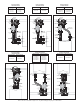
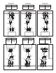
• Note: Not all installation steps applicable to all Manifold styles.
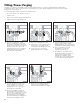
Installation
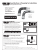
1. Remove the o-ring from the Hydro-Core End(s) and save for reinstallation.
2. Connect the Hydro-Core End (s)
to branch tubing.
3. Loosely connect the Circulator
to the Hydro-Core anged ball valve connection.
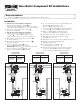
IMPORTANT: The Circulator should pump into the boiler, if applicable.
4. Loosely connect the Hydro-Core End(s)
union nut, o-ring and tting to the
Hydro-Core union ball valve connection.
5. Align the Circulator
into the desired position.
Ensure both pump gaskets are properly aligned.
6. Fully tighten the bolts to the anged connection.
7. Fully tighten the union nut to the Hydro-Core
union ball valve connection.
8. Support the piping assembly with hangers and clamps.
9. Connect the Hydro-Core Manifold
to the remaining hydronic system.
10. Pressure test the system to ensure that all connections are pressure tight.
Caution should be used during all pressure testing to avoid potential personal injury.
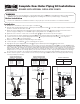
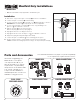
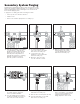
MANIFOLD
Manifold Only Installations
Parts and Accessories
HYDRO-CORE
END
Union Nut
Branch Tubing
Union Ball Valve
Connection
Rotating Flange
Ball Valve
Connection
CIRCULATOR
PUMP
HYDROCORE
MANIFOLD
D
A
G
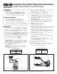
Interested in upgrading your
Manifold Kit to a Complete
or Component kit? Or do you
have an unusual set of system
requirements or a particularly
unique area to work within? Craft
your own kit - all Hydro-Core
components are available for
individual purchase. A solution is
available for any given need.
MANIFOLDS UNION CONNECTIONS
PUMP CONNECTIONS BOILER CONNECTIONS
See www.webstonevalves.com/hydro-core/boilercompatiblity
for a complete list of parts and accessories.
W
W
W
.
W
E
B
S
T
O
N
E
V
A
L
V
E
S
.
C
O
M
15
100
150
200
kPa
psi
50
0
10
5
0
20
25
30
DUAL SCALE
PRESSURE GAUGE