
Install Instructions

3
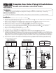
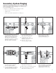
HYDROCORE
MANIFOLD
A
Union Ball Valve
Connection
Union Ball Valve
Connection
SYSTEM SUPPLY
PIPED ASSEMBLY
SYSTEM RETURN
PIPED ASSEMBLY
System Return Port /
Boiler Inlet
System Supply Port /
Boiler Outlet
CB
Union Nut Union Nut
BOILER
HYDROCORE
MANIFOLD
A
Union Ball Valve
Connection
Union Ball Valve
Connection
SYSTEM SUPPLY
PIPED ASSEMBLY
SYSTEM RETURN
PIPED ASSEMBLY
System Return Port /
Boiler Inlet
System Supply Port /
Boiler Outlet
CB
Union Nut Union Nut
BOILER
Union Ball Valve
Connection
Union Ball Valve
Connection
Pressure
Relief
Valve
(150 PSI)
Pressure Relief
Valve (30 PSI)
SYSTEM SUPPLY
PIPED ASSEMBLY
SYSTEM RETURN
PIPED ASSEMBLY
System Return Port /
Boiler Inlet
System Supply
Por t / Boiler
Outlet
Domestic
Water /
Hot Outlet
Domestic
Water /
Cold Inlet
C
B
Union Nut
Union Nut
Pressure
Gauge
HYDROCORE
MANIFOLD
A
BOILER
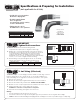
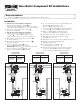
Complete Near Boiler Piping Kit Installations
BOILERS WITH INTERNAL CIRCULATOR PUMPS
WARNING!
• Both end connections of the ex piping are loosely assembled at the factory & MUST be properly tightened as part of product installation.
Caution should be used when handling the ex piping with the end ttings removed due to potential for injury on a sharp edge.
Before Installation
• Review boiler manufacturers’ installation literature for any required/recommended clearances for manifold installation.
Installation
1. Establish the “as installed” location of the Hydro-Core Manifold .
2. Bend the System Supply Piped Assembly and System Return Piped Assembly to the desired path using the maximum radius
possible to minimize the frictional losses.
3. Adjust the System Supply Piped Assembly and System Return Piped Assembly length as desired per the instructions
provided on page 2 making sure to include the length of piping installed into the ttings on both ends.
4. Tighten the end connection on both ends of each ex pipe & per the instructions provided on page 2.
5. Loosely assemble the System Supply Piped Assembly and System Return Piped Assembly to the respective boiler ports.
6. Connect the union nut of the System Supply Piped Assembly and System Return Piped Assembly to the respective
Hydro-Core Manifold ports and fully tighten.
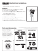
7. Support the near boiler piping assembly with hangers and clamps.
8. Connect the Hydro-Core Manifold to the remaining hydronic system.
9. Fully tighten the System Supply Piped Assembly and System Return Piped Assembly ttings at the boiler.
10. Combi Boiler Kits (4FK5-CH/ 5FK5-CH): Remove side pipe plug from System Supply Piped Assembly and screw the 30 PSI pressure
relief valve into the threaded port. The discharge line from the PRV should pitch downward and terminate 6" above drains where discharge
will be clearly visible. The discharge end of the line shall be plain (unthreaded) and a minimum of 3/4" in diameter. The discharge line
material must be suitable for water at least 180° Fahrenheit. The discharge line shall be as short and straight as possible such that the
arrangement does not reduce the relieving capacity of the pressure relief valve. No valve of any type may be installed in the discharge
line of the pressure relief valve. See included Isolator EXP/E2/E3 directions for Domestic Water installation and servicing directions.
11. Pressure test the system to ensure that all connections are pressure tight. Caution should be used during all pressure testing
to avoid potential personal injury.
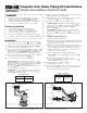
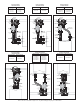
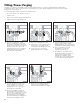
FOR WALL HUNG BOILERS WITH
INTERNAL CIRCULATOR PUMPS
IPS System Piping SWT System Piping
4FK3-WIF
4FK4-WIF
4FK3-WIS
5FK3-WIF
5FK4-WIF
5FK3-WIS
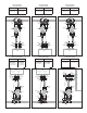
FOR WALL HUNG BOILERS WITH
INTERNAL CIRCULATOR PUMPS
IPS System Piping SWT System Piping
4FK3-WIF-18
4FK4-WIF-18
4FK3-WIS-18
5FK3-WIF-18
5FK4-WIF-18
5FK3-WIS-18
FOR SELECT COMBI BOILERS
IPS System Piping SWT System Piping
4FK5-CH 5FK5-CH
Boilers shown for illustration purposes only.
COMPLETE NEAR
BOILER PIPING KITS