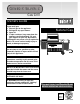
GENESIS SILVER–C ® Gas Grill Owners Guide ® ® R WE B E WE B R WARNING Do not store or use gasoline or other flammable liquids or vapors within 25 feet (8m) of this appliance. Natural Gas E DANGER If you smell gas: 1. Shut off gas to the appliance. 2. Extinguish any open flames. 3. Open lid 4. If odor continues, keep away from the appliance and immediately call your gas supplier or your fire department.
DANGER Failure to follow the Dangers, Warnings and Cautions contained in this Owner’s Manual may result in serious bodily injury or death, or in a fire or an explosion causing damage to property. WARNINGS Do not store a spare or disconnected liquid propane cylinder under or near this barbecue. Improper assembly may be dangerous. Please carefully follow the assembly instructions in this manual.
Warranty Weber-Stephen Products Co.
Contents Danger & Warnings ................................ A-2 Warranty ................................................. A-3 General Instructions ............................... A-5 Exploded View ........................................ A-6 Parts List ................................................ A-9 Assembly Instructions ............................ B-1 Installing Features .................................. C-1 Operating ............................................... D-1 Lighting ....................
Storage General Instructions • Your Weber Gas Barbecue is a portable outdoor cooking appliance. With the Weber Gas Barbecue you can grill, barbecue, roast and bake with results that are difficult to duplicate with indoor kitchen appliances. The closed lid and Flavorizer® Bars produce that “outdoor” flavor in the food. The Weber Gas Barbecue is portable so you can easily change its location in your yard or on your patio. Portability means you can take your Weber Gas Barbecue with you if you move.
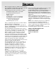
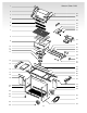
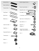
Genesis Silver-C NG 1 2 27 3 28 4 29 5 30 31 32 33 6 7 8 34 9 35 10 36 11 12 13 37 38 39 40 14 41 42 15 43 16 44 45 46 33 17 18 19 47 18 20 21 48 49 22 23 50 24 51 25 52 26 A-6
1. 2. 3. 4. 5. 6. 7. 8. 9. 10. 11. 12. 13. 14. 15. 16. 17. 18. 19. 20. 21. 22. 23. 24. 25. 26. Hinge Pin Left Endcap Shroud Handle Warm-Up Basket Warming Rack Cooking Grates Flavorizer Bars Cooking Box 1/4-20 keps nut Slide Out Bottom Tray Catch pan holder Catch pan Left Frame Left Trim Piece Work Surface Front Panel Hinge Rod Left Swing-Up Work Surface Caster Frame 1/4-20 x 2 inch bolts Bottom Shelf Frame Connectors Casters Wheels Hubcap 27. 28. 29. 30. 31. 32. 33. 34. 35. 36. 37. 38. 39. 40. 41. 42. 43.
© 1999 Weber-Stephen Products Co., Weber, the silhouette, and the kettle configuration are registered trademarks of Weber-Stephen Products Co., 200 East Daniels Road, Palatine, IL, 60067-6266, U.S.A. This product is covered by one or more United States patents and patents in other nations globally. Printed in the U.S.A.
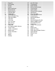
Screwdriver Left Frame - 1 Phillips screwdriver Hammer Right Frame - 1 7/16 open-end or an adjustable wrench Wheel Frame - 1 Pliers Caster Frame - 1 Block of wood Lid - 1 Frame Connectors - 2 ® ® Left Trim Piece - 1 Right Trim Piece - 1 Cooking Box - 1 Work Surface - 1 Left Swing-Up Work Surface - 1 Cooking grates - 2 Right Swing-Up Work Surface Hinge Rod - 2 Control panel - 1 Bottom Shelf - 1 Wheel Axle - 1 A-9
Warming Rack - 1 Manifold Support Bracket - 1 Warm-Up Basket - 1 Burner Control Knobs - 3 Flavorizer Bars - 5 Hinge Pins (1/4 x 1 1/2 inch clevis pin) - 2 Front Panel - 1 2 inch bolts (1/4 x 20 x 2 inch bolts) - 5 Back Panel - 1 1/2 inch bolts (1/4 x 20 x 1/2 inch bolts) - 8 Bottom tray - 1 Keps Nut (1/4 x 20 Keps Nut) - 1 Nylon Washers - 13 Catch Pan Holder - 1 Cotter Pin - 2 Hubcaps - 3 Catch-Pan - 1 Control Panel Hardware (Phillips screws/washers) - 2 Disposable Drip Pans - 2 Hose - 1 Thermo
Assembly Instructions Assemble frame You will need: left frame, right frame, two 1/2 inch bolts, two nylon washers and a 7/16 inch or adjustable wrench. Note - Work on carpeted area (on grass or one of the boxes) to protect the finish during frame assembly. Lay the leg frame pieces as shown so the leg tabs point up. 1) Connect the two frame pieces with the tabs inside of the frame. 2) Slip washers on bolts, then insert bolts as shown and tighten.
Continue frame assembly You will need: caster frame and wheel frame. Place the caster frame onto the tabs of the left frame, so that the swing table locking bracket (1) is to the rear. Place the wheel frame onto the tabs of the right frame, so that the swing table locking bracket is to the rear (2). The leg tabs must be on the inside of the frames. Add back panel You will need: frame assembly, back panel, two 1/2 inch bolts, two nylon washers, and a 7/16 or adjustable wrench.
Insert casters You will need: frame assembly and two casters. Push the casters firmly into the inserts in the ends of the caster frame. Slide the cooking box (assembly) to the left within the frame assembly. Add the nylon washer to the bolt. Insert the bolt through the cooking box and frame with the head of the bolt outside the box. Add the keps nut. Tighten by holding the bolt with pliers while you tighten the nut with a wrench.
Your Weber Gas Grill Manifold assembly consisting of gas manifold, valves and gas burners has been factory assembled, pressure- and flame- tested. As a safety precaution, we recommend you check the burner alignment: 1) Are the ends of the burners under the washers at the left rear and left front of the cooking box? The screws are only guides. Do not tighten. 2) Do the valves fit into the ends of the burners? 3) Are the wing nuts under the burner assembly hand tight? Do not tighten with pliers.
Gas Line Piping ■ If the length of the line required does not exceed 50 feet, use a 5/8" O.D. tube. One size larger should be used for lengths greater than 50 feet. ■ Gas piping may be copper tubing, type K or L; polyethylene plastic tube, with a minimum wall thickness of .062 inch; or standard weight (schedule 40) steel or wrought iron pipe. ■ Copper tubing must be tin-lined if the gas contains more than 0.3 grams of hydrogen sulfide per 100 cubic feet of gas.
Check that all burner valves are off You will need: burner control knobs. Valves are shipped in the OFF position, but you should check to be sure that they are turned OFF. Put the knob on each valve. Check by pushing down and turning clockwise. If they do not turn, they are off. Proceed to the next step. If they do turn continue turning them clockwise until they stop, then they are off. Proceed to the next step.
Install the slide out bottom tray You will need: the slide out bottom tray(1), catch pan holder(2), catch pan and one disposable drip pan. (1) Slide the bottom tray onto the mounting rails under the cooking box with finger grip toward you(1). WARNING: Do not line bottom tray with aluminum foil. It can cause grease fires by trapping the grease and not allowing grease to flow into the catch pan. (2) Hook the ends of the catch pan holder into the hole in the slide out bottom tray.
Install Lid You will need: lid, two hair pin cotters(1) and two hinge pins(2). Place lid on top of the cooking box. Align the hinges at the rear of the barbecue. Insert hinge pins through the hinges from the outside. Insert hair pin cotters into the small holes in the hinge pins. Install control panel and burner control knobs You will need: control panel, two Phillips screws/ washers, a Phillips screwdriver, and burner control knobs. 1) Set the control panel in place over both frame braces.
Installing Features Install the right end trim piece with tool holders and right swing-up work surface You will need: Right trim piece with tool holders, right swing-up work surface, swing-up work surface rod, one 1/2 inch bolt, one nylon washer and a wrench 1.) Start the right end trim piece into the frame as shown, do not push the trim piece in all of the way and do not add bolt yet. 3.) Insert one end of the swing-up work surface rod into the hole in the frame. (1) 2.
4.) While holding swing-up work surface in position, insert the other end of the swing-up work surface rod into the right end trim piece (1). Push the trim piece into the frame as shown, making sure that the tab on the back underside piece of the trim piece is snapped into the slot in the rear frame (2). To raise swing-up work surface: Lift table all the way up and slide it to the left, then lower table until you feel it lock in the up position.
Install side burner You will need: side burner, m WARNING: Make sure gas supply is off. Start the side burner hose into the opening between the control panel and right trim piece. Set the side burner in place in the frame. The side burner locking clip on the right should latch under the right trim piece. Route the hose between the cylinder panel and wheel frame. Tilt the side burner slightly, toward the control panel. Latch the side burner locking clip on the left, under the control panel.
Install the left end trim piece and swing-up work surface You will need: End trim piece, swing-up work surface, swing-up work surface rod, two 1/2 inch bolts, two nylon washers and a wrench 1.) Start the left end trim piece into the frame as shown, do not push the trim piece in all of the way and do not add bolts yet. Connect the side burner hose as follows: 1) Slide back the collar of the quick disconnect on the manifold.
4.) While holding swing-up work surface in position, insert the other end of the swing-up work surface rod into the left end trim piece. Push the trim piece into the frame. To raise swing-up work surface: Lift table all the way up and slide it to the right, then lower table until you feel it lock in the up position. To lower swing-up work surface: Lift table up until it disengages and slide it to the left.
To perform leak checks: Slide back the collar of the quick disconnect. Push the male fitting of the hose into the quick disconnect, and maintain pressure (1). Slide the collar closed (2). If it does not engage or lock, repeat procedure. Gas will not flow unless the quick disconnect is properly engaged. Check for gas leaks m DANGER Do not use an open flame to check for gas leaks. Be sure there are no sparks or open flames in the area while you check for leaks.
Check: 1) Hose to manifold connection 2) Manifold to side burner hose connection m WARNING: If there is a leak at connection(1), retighten the fitting with a wrench and recheck for leaks with soap and water solution. If a leak persists after retightening the fitting, turn OFF the gas. DO NOT OPERATE THE BARBECUE. Contact the Customer Service Representative in your region using the contact information sheet provided with your manual.
Installing the warming rack You will need: warming rack. Set the warming rack into the slots at the rear of the cooking box. Install the bottom shelf You will need: Bottom shelf. Set the bottom shelf in place between the two frame connectors underneath the cooking box. Install the thermometer You will need: Thermometer. Insert the thermometer into its holder on the right side of the lid.
Operating Lighting 1) Open the lid. 2) Make sure all burner control knobs are turned OFF. (Push each burner control knob down and turn clockwise to ensure that they are in the off position.) 3) Turn the gas supply valve on. WARNING: Do not lean over the open barbecue. Keep your face and body at least one foot away from the matchlight hole when lighting the barbecue. 4) Push Front burner control knob down and turn to START/HI. 5) Push the Crossover Ignition Button several times, so it clicks each time.
WARNING: If the burner does not light, turn the Front burner control knob to OFF and wait 5 minutes to let the gas clear before you try again or try to light with a match. 7) After the FRONT burner is lit you can turn on the other burner or burners. Note - Always light the FRONT burner first. The other burner or burners ignite from the FRONT burner.
Lighting the Side Burner Lighting the side burner if the main burners are lit. 1) Open the side burner lid. 2) Push down and turn the side burner control to HI. 3) Press the side burner igniter button several times so it clicks each time. The side burner has a separate ignition system from the main cooking box.
■ Check that the areas under the control panel and the slide out bottom tray are free from debris that might obstruct the flow of combustion or ventilation air. ■ The Spider stopper guards should also be checked for any obstructions. (See “Maintenance” Section.) Cooking WARNING: Do not move the Weber Gas Barbecue when operating or while barbecue is hot. You can adjust the FRONT and BACK burners as desired.
Check: 1) Hose to manifold connections. WARNING: If there is a leak at connection (1), retighten the fitting with a wrench and recheck for leaks with a soap and water solution. If a leak persists after re-tightening the fitting, turn OFF the gas. DO NOT OPERATE THE BARBECUE. Contact the Customer Service Representative in your region using the contact information sheet provided with your manual.
Main Burner Flame Pattern General Maintenance The Weber Gas Barbecue burners have been factory set for the correct air and gas mixture. The correct flame pattern is shown. 1) Burner tube 2) Tips occasionally flicker yellow 3) Light blue 4) Dark blue Weber Spider Stopper™ Guards Your Weber Gas Barbecue, as well as any outdoor gas appliance, is a target for spiders and other insects. They can nest in the venturi section (Venturi(1), air shutter(2), venturi fin(3) ) of the burner tubes.
7) Lift and twist the burner assembly slightly, to separate the crossover tube(1) from the burners. Remove the burners from the cooking box. Replacing Main Burners 1) Your Weber Gas Barbecue must be OFF and cool. 2) Turn gas OFF at source. 3) To remove control panel: take off the burner control knobs. Remove the screws holding the control panel in place. Lift off the control panel. 4) Unlatch the Spider Stopper™ Guards and remove them. (1) 8) To reinstall the burners, reverse 3) through 7).
9) Reinstall the Spider Stopper Guards. Slightly rotate the Spider Stopper Guards so that the seams are in line with the Venturi fins(1). There should be no gaps in the seams or in the fit around the burners(2) and valves(3). Crossover® Ignition System Operations If the Crossover Ignition System fails to ignite the Left burner, light the Left burner with a match. If the Left burner lights with a match, then check the Crossover Ignition System.
Troubleshooting Problem Check Cure Burners burn with a yellow or orange flame, in conjunction with the smell of gas. Inspect Weber Spider Stopper Guards for possible obstructions. (Blockage of holes.) Clean Weber Spider Stopper Guards. (See Section “Annual Maintenance”) Burner does not light, or flame is low in HIGH position. Is fuel hose bent or kinked? Straighten fuel hose.
Side Burner Troubleshooting WARNING: Before attempting any troubleshooting steps, all gas controls and supply valves should be in the OFF position. Problem Check Cure Side Burner does not light. Is gas supply off? Turn supply on. Flame is low in HIGH position. Is the fuel hose bent or kinked? Straighten hose. Flame is very yellow in conjunction with the smell of gas, Inspect the Weber Spider Stopper Guard for possible obstructions. (lockage of holes.) Clean Weber Spider Stopper Guard.