GENESIS SILVER–B ® Gas Grill Owners Guide Liquid Propane Gas ® WARNING 1. Do not store spare liquid propane cylinder within 10 feet (3m) of this appliance. 2. Do not store or use gasoline or other flammable liquids or vapors within 25 feet (8m) of this appliance. ® R WE B E WE B E DANGER If you smell gas: 1. Shut off gas to the appliance. 2. Extinguish any open flames. 3. Open lid 4. If odor continues, keep away from the appliance and immediately call your gas supplier or your fire department.
DANGER Failure to follow the Dangers, Warnings and Cautions contained in this Owner’s Manual may result in serious bodily injury or death, or in a fire or an explosion causing damage to property. WARNINGS Do not store a spare or disconnected liquid propane cylinder under or near this barbecue. Improper assembly may be dangerous. Please carefully follow the assembly instructions in this manual.
Warranty Weber-Stephen Products Co.
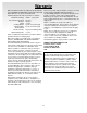
Contents Danger & Warnings ................................ A-2 Warranty ................................................. A-3 General Instructions ............................... A-5 Exploded View ....................................... A-6 Parts List ................................................ A-9 Assembly Instructions ............................ B-1 Installing Features .................................. C-1 Operating ............................................... D-1 Lighting .....................
Storage General Instructions • Your Weber Gas Barbecue is a portable outdoor cooking appliance. With the Weber Gas Barbecue you can grill, barbecue, roast and bake with results that are difficult to duplicate with indoor kitchen appliances. The closed lid and Flavorizer® Bars produce that “outdoor” flavor in the food. The Weber Gas Barbecue is portable so you can easily change its location in your yard or on your patio. Portability means you can take your Weber Gas Barbecue with, if you move.
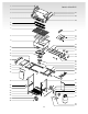
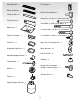
1 Genesis Silver-B LP 2 3 27 28 4 29 5 6 7 30 31 32 33 8 9 34 35 36 37 10 11 12 38 13 39 14 40 41 42 43 44 32 15 16 17 18 45 46 19 47 20 48 21 49 22 50 23 51 24 52 25 26 53 54 A-6
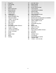
1. 2. 3. 4. 5. 6. 7. 8. 9. 10. 11. 12. 13. 14. 15. 16. 17. 18. 19. 20. 21. 22. 23. 24. 25. 26. Hinge Pin Left Endcap Shroud Handle Warm-Up Basket Warming Rack Cooking Grate Flavorizer Bar Cooking Box 1/4-20 keps nut Slide Out Bottom Tray Catch pan holder 1/4-20 x 1/2 inch bolt Left Trim piece Work Surface Left Frame Hinge Rod Left Swing-Up Work Surface Caster Frame 1/4-20 x 2 inch bolt 1/4 Inch Nylon Washer Frame Connector Caster Bottom Shelf Wheel Hubcap 27. 28. 29. 30. 31. 32. 33. 34. 35. 36. 37. 38.
© 1999 Weber-Stephen Products Co., Weber, the silhouette, and the kettle configuration are registered trademarks of Weber-Stephen Products Co., 200 East Daniels Road, Palatine, IL, 60067-6266, U.S.A. This product is covered by one or more United States patents and patents in other nations globally. Printed in the U.S.A.
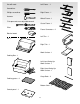
You will need: Left Frame - 1 Screwdriver Phillips screwdriver Right Frame - 1 Hammer Wheel Frame - 1 7/16 open-end or an adjustable wrench Caster Frame - 1 Pliers Frame Connectors - 2 Block of wood Left Trim - 1 Lid - 1 Right Trim - 1 ® ® Work Surface - 1 Cooking Box - 1 Left-Hand Swing-Up Work Surface - 1 Right-Hand Swing-Up Work Surface - 1 Hinge Rods - 2 Cooking grates - 2 Bottom Shelf - 1 Control panel - 1 A-9
Warming Rack - 1 Fuel Guage - 1 Warm-Up Basket - 1 Burner Control Knobs - 3 Flavorizer Bars - 5 Hinge Pins (1/4-20 x 1 1/2 inch clevis pin) - 2 Cylinder Panel - 1 2 inch bolts (1/4-20 x 2 inch bolts) - 5 Bottom tray - 1 1 3/4 inch bolts (1/4-20 x 1 3/4 inch bolts) - 2 Catch Pan Holder - 1 1/2 inch bolts (1/4-20 x 1/2 inch bolts) - 9 Catch-Pan - 1 Keps Nut (1/4-20 Keps Nut) - 1 Disposable Drip Pans - 2 Nylon Washers - 16 Hair Pin Cotter - 2 Manifold Support Bracket - 1 Hubcaps - 3 Thermometer - 1 Co
Assembly Instructions Assemble frame You will need: left frame, right frame, two 1/2 inch bolts, two nylon washers and a 7/16 inch or adjustable wrench. Note - Work on carpeted area (on grass or one of the boxes) to protect the finish during frame assembly. Lay the leg frame pieces as shown so the leg tabs point up. 1) Connect the two frame pieces with the tabs inside of the frame. 2) Slip washers on bolts, then insert bolts as shown and tighten.
Continue frame assembly You will need: caster frame, wheel frame, four 1/2 inch bolts, four nylon washers and a 7/16 inch or adjustable wrench. Place the caster frame onto the tabs of the left frame, so that the swing table locking latch (1) is to the rear. Place the wheel frame onto the tabs of the right frame, so that the swing table locking latch (2) is to the rear. The leg tabs must be on the inside of the frames. Add the washers to the bolts.
Insert casters You will need: frame assembly and two casters. Push the casters firmly into the inserts in the ends of the caster frame. Slide the cooking box (assembly) to the left within the frame assembly. Add the nylon washer to the bolt. Insert the bolt through the frame and cooking box with the head of the bolt outside the box. Add the keps nut. Tighten by holding the bolt with pliers while you tighten the nut with a wrench.
Install manifold bracket You will need: manifold bracket. Hook the bracket(2) onto the manifold at the center burner valve. Place your hand underneath the bracket. Lift the manifold, bracket and cooking box slightly, then hook the tab of the bracket onto the frame brace(1). Install cylinder panel You will need: Cylinder panel, two 1 3/4inch bolts, two nylon cylinder glides, two nylon washers a 7/16 inch or adjustable wrench and pliers. Insert the cylinder panel tabs(1) into the slots in the frame brace(2).
Add fuel gauge You will need: fuel gauge, two wing nuts and two nylon washers. 1) Slip the bolts on the back of the fuel gauge through the two small holes in the cylinder panel. 2) Add washers to the bolts, then wing nuts, and tighten with your fingers. 3) Tighten the igniter lock nut back onto the igniter. Note - If the igniter works loose, carefully tighten the igniter lock nut with an adjustable wrench or pliers.
Fill liquid propane cylinder Note - The liquid propane cylinder manufacturer is responsible for the materials, workmanship and performance of the cylinder. If the cylinder has a defect, malfunctions, or you have a question regarding the cylinder, call the cylinder manufacturer’s customer service center. The phone number is on the warning decal, which is permanently attached to the cylinder.
Check that all burner valves are off You will need: burner control knobs. Valves are shipped in the OFF position, but you should check to be sure that they are turned OFF. Put the knob on each valve. Check by pushing down and turning clockwise. If they do not turn, they are off. Proceed to the next step. If they do turn continue turning them clockwise until they stop, then they are off. Proceed to the next step. Remove plastic dust cover from the fuel cylinder valve.
Check: 1) Hose to manifold connection. WARNING: If there is a leak a connection(1), retighten the fitting with a wrench and recheck for leaks with soap and water solution. If a leak persists after retightening the fitting, turn OFF the gas. DO NOT OPERATE THE BARBECUE. Contact the Customer Service Representative in your region using the contact information sheet provided with your manual.
Install the slide out bottom tray You will need: the slide out bottom tray(1), catch pan holder(2), catch pan and one disposable drip pan. Install Lid You will need: lid, two hair pin cotters(1) and two hinge pins(2). Place lid on top of the cooking box. Align the hinges at the rear of the barbecue. Insert hinge pins through the hinges from the outside. Insert hair pin cotters into the small holes in the hinge pins.
Installing Features Install the right end trim piece with tool holders and right swing-up work surface You will need: Right trim piece with tool holders, right swing-up work surface, swing-up work surface rod, one 1/2 inch bolt, one nylon washer and a wrench 1.) Start the right end trim piece into the frame as shown, do not push the trim piece in all of the way and do not add bolt yet. 3.) Insert one end of the swing-up work surface rod into the hole in the frame. (1) 2.
4.) While holding swing-up work surface in position, insert the other end of the swing-up work surface rod into the right end trim piece (1). Push the trim piece into the frame as shown, making sure that the tab on the back underside piece of the trim piece is snapped into the slot in the rear frame (2). 5.) Add a washer to the bolt and insert it through the front hole in the frame and the hole in the trim piece. Tighten with a wrench.
To raise swing-up work surface: Lift table all the way up and slide it to the left, then lower table until you feel it lock in the up position. Install the left end trim piece and swing-up work surface You will need: End trim piece, swing-up work surface, swing-up work surface rod, two 1/2 inch bolts, two nylon washers and a wrench 1.) Start the left end trim piece into the frame as shown, do not push the trim piece in all of the way and do not add bolts yet.
4.) While holding swing-up work surface in position, insert the other end of the swing-up work surface rod into the left end trim piece. Push the trim piece into the frame. To raise swing-up work surface: Lift table all the way up and slide it to the right, then lower table until you feel it lock in the up position. To lower swing-up work surface: Lift table up until it disengages and slide it to the left.
Install control panel and burner control knobs You will need: control panel, two Phillips screws/ washers, a Phillips screwdriver, and burner control knobs. 1) Set the control panel in place over both frame braces. Hold the Crossover Ignition button up while setting the control panel in place. 2) While looking under the right trim piece push the control panel down and line up the holes in the control panel with the white plastic plugs in the frame brace.
Install Flavorizer® Bars and Cooking Grates You will need: five Flavorizer Bars and two cooking grates. Place the Flavorizer Bars side by side in the cooking box. Installing the warming rack You will need: warming rack. Set the warming rack into the slots at the rear of the cooking box. Install the thermometer You will need: Thermometer. Insert the thermometer into its holder on the right side of the lid. Set the cooking grates onto the ledges in the cooking box with the rounded sides up.
Operating m DANGER: When the “excess gas flow control” feature is activated, a small amount of gas I still flowing to the burners. After turning OFF the cylinder knobs, wait at least 5 minutes for the gas to clear before attempting to light the barbecue. Failure to do so may result in an explosive flame-up, which can cause serious bodily injury or death. 3) Turn the cylinder on by turning the cylinder valve counterclockwise. m WARNING: Do not lean over the open barbecue.
3) Turn the cylinder on by turning the cylinder valve counterclockwise. 4) Strike a match and put the flame into the matchlight hole in the front of the cooking box. m WARNING: Do not lean over open barbecue. Keep your face and body at least one foot away from the matchlight hole when lighting the barbecue. 5) Push Front burner control knob down and turn to START/HI. 6) Check that the burner is lit by looking through the matchlight hole on the front of the cooking box.
■ The Weber Gas Barbecue should be checked for gas leaks and any obstructions in the burner tubes before using. (See Sections: “General Maintenance and Annual Maintenance.”) ■ Check that the areas under the control panel and the slide out bottom tray are free from debris that might obstruct the flow of combustion or ventilation air. ■ The Spider Stopper ™ Guards should also be checked for any obstructions. (See Section: “Annual Maintenance.
This is a secondary device to prevent the overfilling of your LP cylinder. The proper filling methods for the filling of your cylinder are by weight or volume, as described in NFPA 58. Please make sure your filling station fills your LP cylinder by weight or volume. Ask your filling station to read purging and filling instructions on the LP cylinder before attempting to fill. mWARNING: Do not exchange the LP tank provided with your barbecue, unless the exchange LP tank is equipped with an OPD.
7) Check for leaks by wetting the fitting with the soap and water solution and watching for bubbles. If bubbles form, or if a bubble grows, there is a leak. 2) Loosen the cylinder lock wing nut. Swing the cylinder lock down. Tighten the wing nut. To Connect the hose to the cylinder: 3) Remove the plastic dust cover from the valve. 4) Screw the regulator coupling onto the tank valve, clockwise, or to the right. Hand-tighten only. Note: This is a new type of connection.
Liquid Propane (LP) Cylinder(s) Safe handling tips for Liquid Propane Gas Cylinders ■ The joint where the hose connects to the LP cylinder must be leak tested each time the LP cylinder is reconnected. For example, test each time the LP cylinder is refilled. ■ Be sure the regulator is mounted with the small vent hole pointed downward so that it will not collect water. This vent should be free of dirt, grease, bugs etc.
Contact the Customer Service Representative in your region using the contact information sheet provided with your manual. Check: 3) Valves-to-manifold connections. 4) The hose-to-regulator connection. m WARNING: If there is a leak at connections (2), (3) or (4), turn OFF the gas. DO NOT OPERATE THE BARBECUE. Contact the Customer Service Representative in your region using the contact information sheet provided with your manual.
Main Burner Flame Pattern General Maintenance The Weber Gas Barbecue burners have been factory set for the correct air and gas mixture. The correct flame pattern is shown. 1) Burner tube 2) Tips occasionally flicker yellow 3) Light blue 4) Dark blue Weber Spider Stopper™ Guards Your Weber Gas Barbecue, as well as any outdoor gas appliance, is a target for spiders and other insects. They can nest in the venturi section (Venturi(1), air shutter(2), venturi fin(3) ) of the burner tubes.
7) Lift and twist the burner assembly slightly, to separate the crossover tube(1) from the burners. Remove the burners from the cooking box. Replacing Main Burners 1) Your Weber Gas Barbecue must be OFF and cool. 2) Turn gas OFF at source. 3) To remove control panel: take off the burner control knobs. Remove the screws holding the control panel in place. Lift off the control panel. 4) Unlatch the Spider Stopper™ Guards and remove them. (1) 8) To reinstall the burners, reverse 3) through 7).
9) Reinstall the Spider Stopper Guards. Slightly rotate the Spider Stopper Guards so that the seams are in line with the Venturi fins(1). There should be no gaps in the seams or in the fit around the burners(2) and valves(3). Crossover® Ignition System Operations If the Crossover Ignition System fails to ignite the Left burner, light the Left burner with a match. If the Left burner lights with a match, then check the Crossover Ignition System.
Troubleshooting Problem Check Cure Burners burn with a yellow or orange flame, in conjunction with the smell of gas. Inspect Weber Spider Stopper Guards for possible obstructions. (Blockage of holes.) Clean Weber Spider Stopper Guards. (See Section “Annual Maintenance”) Burners do not light. -or- Burners have a small flickering flame in the HIGH position. -orBarbecue temperature only reaches 250˚ to 300˚ in the HIGH position.