
User Manual

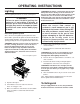


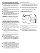


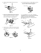
Table Of Contents
- DANGER
- WARNINGS
- WARRANTY
- LP Tank
- PATENTS AND TRADEMARKS
- Contents
- FEATURES
- General Instructions
- For Installation in Canada
- Storage
- Operating area
- Assembly
- Tools needed
- Supplies needed
- Check package contents
- Assemble wheels
- Assemble frame
- Continue frame assembly
- Complete frame assembly
- Insert casters
- Add cooking box
- Install manifold bracket
- Install tank panel assembly
- Add fuel scale assembly
- Install igniter
- Set LP fuel scale
- Fill LP tank
- Check that the burner valves are off
- Connect LP tank
- Check for gas leaks
- Install Flavorizer Bars and Cooking Grates
- Install the bottom tray
- Install the lid
- Install tool holders, control panel and burner control knobs
- Install swing table
- Complete accessory installation
- OPERATING INSTRUCTIONS
- Lighting
- Crossover Ignition System
- To Extinguish
- Manual Lighting
- To Extinguish
- Cooking
- Storage and/or Nonuse
- Periodic Cleaning
- Refilling the LP tank
- Removal of the LP tank
- Connecting the filled LP tank
- LP Tank
- Safe handling tips for LP Gas
- Liquid Propane (LP) Tank(s)
- Annual Maintenance
- Inspection and Cleaning of the Weber Spider Stopper Guards
- General Maintenance
- Weber Spider Stopper Guards
- Main Burner Flame Pattern
- Main Burner Cleaning Procedure
- Replacing Main Burners
- Crossover Ignition System Operations
- TROUBLESHOOTING
- Parts List
- A FINAL WORD OF THANKS
30
Crossover tube
Figure 17
Figure 14
View from behind
cooking box
Wing nuts
Figure 15
Guide screw
Figure 16
d) Unlatch the Spider Stopper Guards and remove.
Figure 14.
e) Remove the manifold bracket and unscrew the two
wing nuts that hold the manifold to the cooking box.
Pull the manifold and valve assembly out of the
burners and carefully set it down. Figure 15.
f) Slide the burner assembly out from under the guide
screw and washer in the corners of the cooking box.
Figure 16.
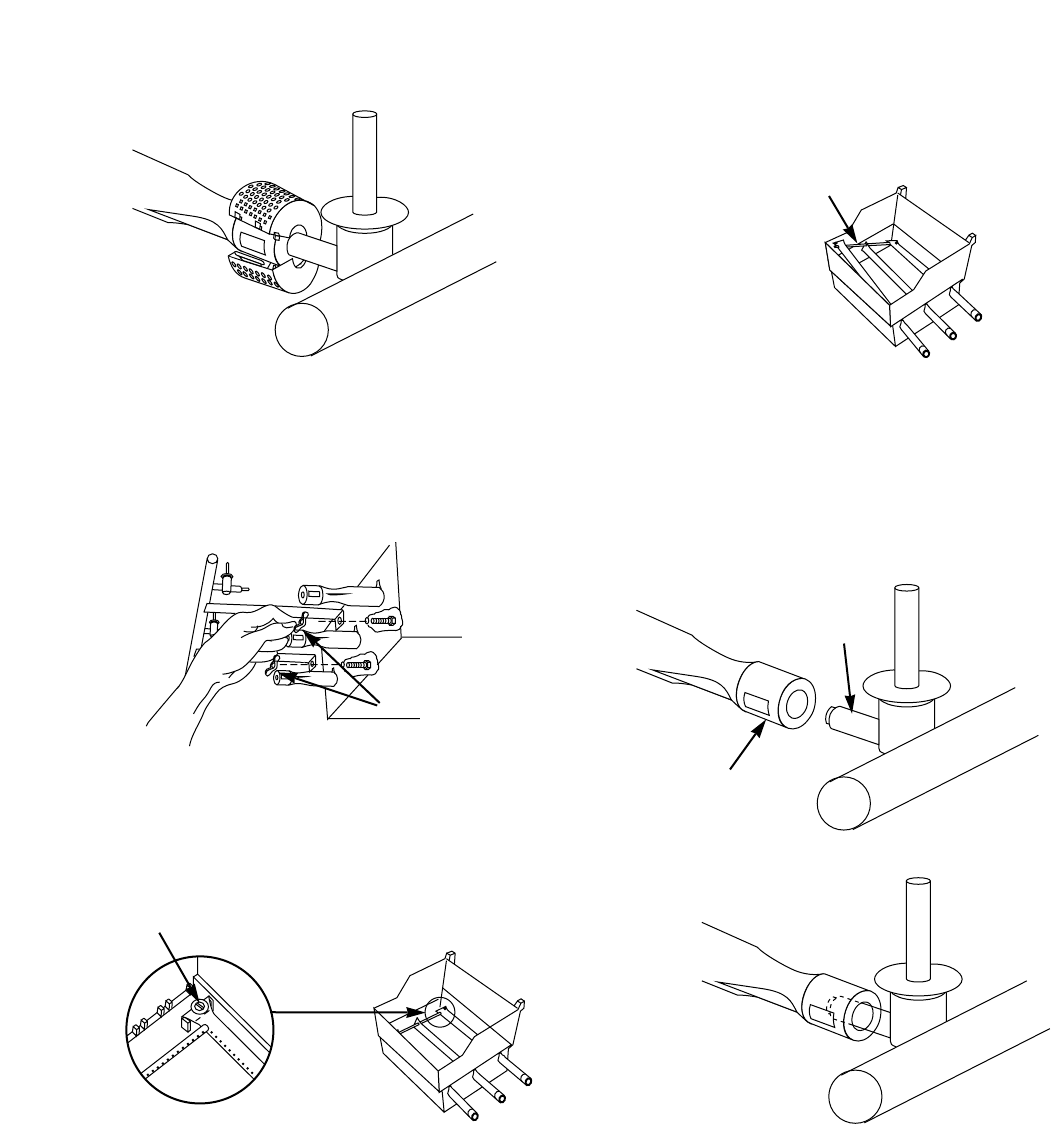
g) Lift and twist the burner assembly slightly, to separate
the crossover tube from the burners. Figure 17.
Remove the burners from the cooking box.
Figure 18
Valve
Burner
(a)
(b)
h) To reinstall burners, reverse steps c) through g).
CAUTION: The burner openings must be positioned
properly over the valve orifices. Figure 18a.
Check proper assembly before fastening manifold in
place. Figure 18b.