
User Manual

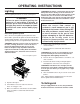


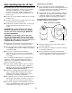


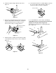
Table Of Contents
- DANGER
- WARNINGS
- WARRANTY
- LP Tank
- PATENTS AND TRADEMARKS
- Contents
- FEATURES
- General Instructions
- For Installation in Canada
- Storage
- Operating area
- Assembly
- Tools needed
- Supplies needed
- Check package contents
- Assemble wheels
- Assemble frame
- Continue frame assembly
- Complete frame assembly
- Insert casters
- Add cooking box
- Install manifold bracket
- Install tank panel assembly
- Add fuel scale assembly
- Install igniter
- Set LP fuel scale
- Fill LP tank
- Check that the burner valves are off
- Connect LP tank
- Check for gas leaks
- Install Flavorizer Bars and Cooking Grates
- Install the bottom tray
- Install the lid
- Install tool holders, control panel and burner control knobs
- Install swing table
- Complete accessory installation
- OPERATING INSTRUCTIONS
- Lighting
- Crossover Ignition System
- To Extinguish
- Manual Lighting
- To Extinguish
- Cooking
- Storage and/or Nonuse
- Periodic Cleaning
- Refilling the LP tank
- Removal of the LP tank
- Connecting the filled LP tank
- LP Tank
- Safe handling tips for LP Gas
- Liquid Propane (LP) Tank(s)
- Annual Maintenance
- Inspection and Cleaning of the Weber Spider Stopper Guards
- General Maintenance
- Weber Spider Stopper Guards
- Main Burner Flame Pattern
- Main Burner Cleaning Procedure
- Replacing Main Burners
- Crossover Ignition System Operations
- TROUBLESHOOTING
- Parts List
- A FINAL WORD OF THANKS
21
Figure 28
View from front
of barbecue
Notch to the front
Slide bar
View from rear
of barbecue
Support rod
Locked position
Unlocked position
Figure 29
Slide
Step 22
Complete accessory installation
You will need: two work tables, two accessory trays, Warm-
Up Basket, warming rack, thermometer, three tubing plugs
and a hammer.
Insert one end of the Weber Warm-Up Basket into the hole
in the right end of the lid and the other end into the slot in
the left end of the lid. Figure 30 (a).
Set the work tables onto the left and right side rails.
Figure 30 (b).
Set the accessory trays between the two frame connectors.
Figure 30 (c).
Set the warming rack into the slots at the rear of the
cooking box. Figure 30 (d).
Insert the thermometer into its holder. Figure 30 (e).
Insert tubing plugs into the ends of the frame. To fully seat
the plugs, you may have to tap them lightly with a hammer.
Figure 30 (f).
Figure 30
(a)
(d)
(e)
(f)
(b)
(c)
(b)
Position slide bar assembly on the outside of the caster
frame. Put a nylon washer on each 1 3/4 inch screw, insert
screws through frame and slide bar assembly and add
nylon washers and hex nuts. Tighten nuts using a
screwdriver and pliers. Figure 28.
To lower table: Pull support rod up to disengage slide lock,
and lower table. To raise table, lift table up and engage slide
in locked position. Figure 29.
CAUTION: To keep the barbecue stationary, the tabs
on the locking casters should be in the down position.