
User Manual
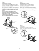
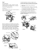


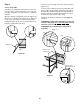
Table Of Contents
- DANGER
- WARNINGS
- WARRANTY
- LP Tank
- PATENTS AND TRADEMARKS
- Contents
- FEATURES
- General Instructions
- For Installation in Canada
- Storage
- Operating area
- Assembly
- Tools needed
- Supplies needed
- Check package contents
- Assemble wheels
- Assemble frame
- Continue frame assembly
- Complete frame assembly
- Insert casters
- Add cooking box
- Install manifold bracket
- Install tank panel assembly
- Add fuel scale assembly
- Install igniter
- Set LP fuel scale
- Fill LP tank
- Check that the burner valves are off
- Connect LP tank
- Check for gas leaks
- Install Flavorizer Bars and Cooking Grates
- Install the bottom tray
- Install the lid
- Install tool holders, control panel and burner control knobs
- Install swing table
- Complete accessory installation
- OPERATING INSTRUCTIONS
- Lighting
- Crossover Ignition System
- To Extinguish
- Manual Lighting
- To Extinguish
- Cooking
- Storage and/or Nonuse
- Periodic Cleaning
- Refilling the LP tank
- Removal of the LP tank
- Connecting the filled LP tank
- LP Tank
- Safe handling tips for LP Gas
- Liquid Propane (LP) Tank(s)
- Annual Maintenance
- Inspection and Cleaning of the Weber Spider Stopper Guards
- General Maintenance
- Weber Spider Stopper Guards
- Main Burner Flame Pattern
- Main Burner Cleaning Procedure
- Replacing Main Burners
- Crossover Ignition System Operations
- TROUBLESHOOTING
- Parts List
- A FINAL WORD OF THANKS
19
Figure 24
Hair pin cotter
Hinge pin
Figure 25
Insert in
frame brace
Tool holders
(a)
(b)
Control panel
Phillips screws/
washers
Step 19
Install the lid
You will need: lid, two hinge pins and two hair pin cotters.
Set the lid in place from the rear of the barbecue. Close and
align the hinge at the rear. Insert hinge pins from the
outside through the hinge. Insert hair pin cotters into the
small holes in the hinge pins. Figure 24.
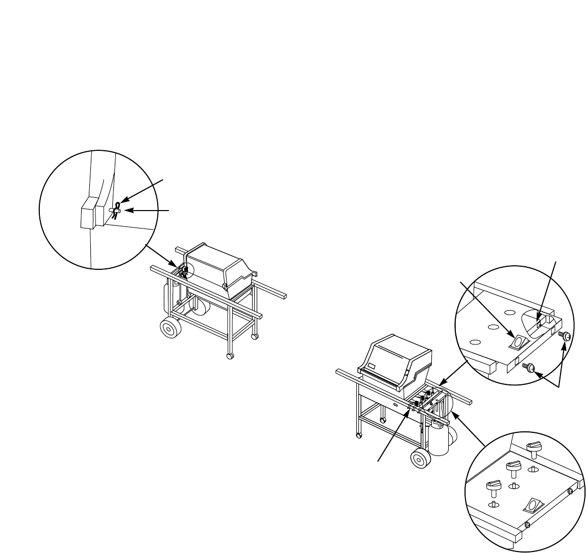
Step 20
Install tool holders, control panel and burner
control knobs
You will need: three tool holders, control panel, two
Phillips screws/washers, a Phillips screwdriver, and three
burner control knobs.
Hook the tool holders over the frame rail. Figure 25.
Set the control panel in place over both frame braces. (Hold
the Crossover Ignition button up while setting the control
panel in place.) Line up the holes in the control panel with
the holes in the inserts in the frame brace. Insert screws
and tighten with a Phillips screwdriver until snug. Do not
overtighten. Figure 25 (a).
Push on the burner control knobs. Figure 25 (b).
Crossover
Ignition Button