
User Manual
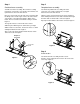
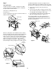


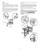
Table Of Contents
- DANGER
- WARNINGS
- WARRANTY
- LP Tank
- PATENTS AND TRADEMARKS
- Contents
- FEATURES
- General Instructions
- For Installation in Canada
- Storage
- Operating area
- Assembly
- Tools needed
- Supplies needed
- Check package contents
- Assemble wheels
- Assemble frame
- Continue frame assembly
- Complete frame assembly
- Insert casters
- Add cooking box
- Install manifold bracket
- Install tank panel assembly
- Add fuel scale assembly
- Install igniter
- Set LP fuel scale
- Fill LP tank
- Check that the burner valves are off
- Connect LP tank
- Check for gas leaks
- Install Flavorizer Bars and Cooking Grates
- Install the bottom tray
- Install the lid
- Install tool holders, control panel and burner control knobs
- Install swing table
- Complete accessory installation
- OPERATING INSTRUCTIONS
- Lighting
- Crossover Ignition System
- To Extinguish
- Manual Lighting
- To Extinguish
- Cooking
- Storage and/or Nonuse
- Periodic Cleaning
- Refilling the LP tank
- Removal of the LP tank
- Connecting the filled LP tank
- LP Tank
- Safe handling tips for LP Gas
- Liquid Propane (LP) Tank(s)
- Annual Maintenance
- Inspection and Cleaning of the Weber Spider Stopper Guards
- General Maintenance
- Weber Spider Stopper Guards
- Main Burner Flame Pattern
- Main Burner Cleaning Procedure
- Replacing Main Burners
- Crossover Ignition System Operations
- TROUBLESHOOTING
- Parts List
- A FINAL WORD OF THANKS
16
Figure 16
Turn so regulator vent
does not collect water
Hose
Tank lock
wing nut
Quick disconnect
engaged
Valve handwheel
close clockwise
Tank valve
Collar
Male
fitting
Pressure
relief valve
Tank
Regulator
Regulator
vent
(a)
(b)
(c)
Figure 15
Figure 14
F
E
Route the hose so it will not interfere with the scale
indicator rod.
The hose and regulator are connected in the following
manner:
Slide back the collar of the quick disconnect on the tank
valve. Push the male fitting of the regulator into the quick
disconnect, and maintain pressure. Slide the collar closed.
Figure 16 (a). Figure 16 (b) shows the quick disconnect
engaged and various components of the tank and
regulator. Regulator vent hole should be at 3, 6, or 9
o'clock. It should not be pointed up. Figure 16 (c).
Step 14
Check that the burner valves are off
You will need: one burner control knob.
Valves are shipped in the OFF position, but you should
check to be sure. Put the knob on each valve. Check by
pushing down and turning clockwise. If they do not turn,
they are off, proceed to the next step. Figure 14.
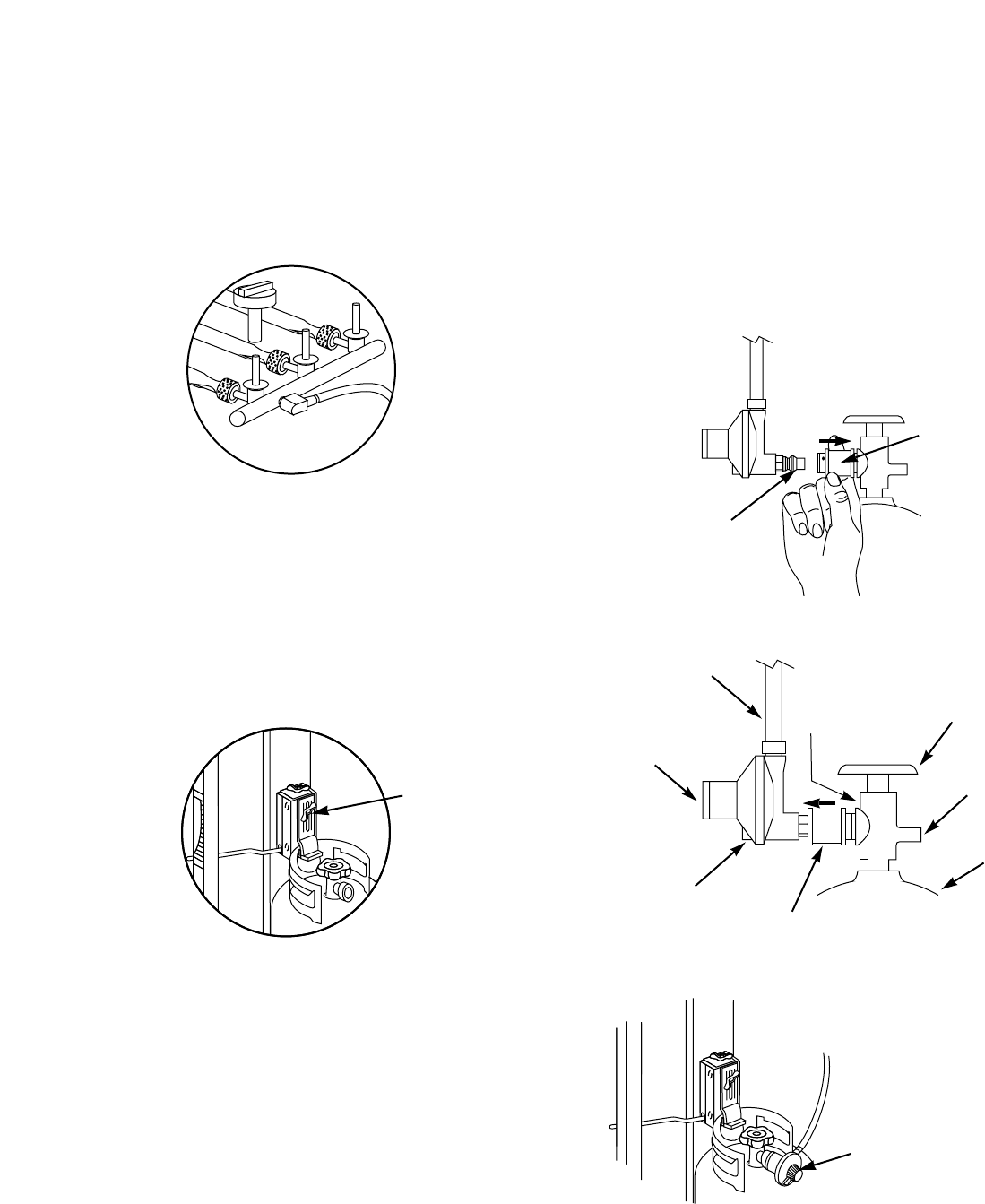
Step 15
Connect LP tank
WARNING: Make sure that the LP tank valve is
closed. Close by turning clockwise.
Hook the LP tank onto the fuel scale. Loosen the tank lock
wing nut. Swing the tank lock down. Tighten the wing nut.
Figure 15.