The Scholastic Series School Bus Heater Operating Instructions Installation Instructions Service Parts Listing For: Webasto Thermosystems Inc. North America 3333 John Conley Drive Lapeer, MI 48446 Phone (810) 245-2400 Toll-free (800) HEATER-1 Fax (810) 664-7720 Technical Assistance Hotline USA: (800) 555-4518 Canada: (800) 667-8900 Org. 2/2001 50000058A www.webasto.
WEBASTO SCHOLASTIC SERIES TABLE OF CONTENTS . . . . . . . . . . . . Table of Contents 1. Introduction 1.1 1.2 1.3 1.4 Scope and Purpose . . . . . . . . . . . . . . . . . . . Meaning of Warnings, Cautions and Notes . Additional Documentation to be Used . . . . . General Safety Regulations and Information 1.4.1 2. . . . . . . . . . . . . . . . . . . . . . . . . . . . . . . . . . . . . . . . . . . . . . . . . . . . . . . . . . . . . . . . . . . . . . . . . . . . . . . . . . . .
TABLE 5.7 OF Fuel System . . . . . . . . . . . . . . . . . . . . . . . . . . . . . . . . . . . . . . . . . . . . . . . . . . . . . . . . . 5-7 5.7.1 5.7.2 5.7.3 5.8 6. . . . . . . . . . . . . . . . . . . . . . . . . . . . . 5-10 . 5-10 . 5-11 . 5-11 . 5-12 . 5-13 . 5-14 . 5-15 . 5-16 Initial Operation . . . . . . . . . . . . . . . . . . . . . . . . . . . . . . . . . . . . . . . . . . . . . . . . . . . . . . . 5-17 Annual Maintenance . . . . . . . . . . . . . . . . . . . . . . . . . . . . . . . . .
WEBASTO SCHOLASTIC SERIES TABLE OF CONTENTS . . . . . . . . . . . . . . . . . . . . . . . . . . . . . . . . . . . . . . . . . . . . . . . . . . . . . . . . . . . . . . . . . . . . . . . . . . . . . . . . . . . . . . . . . . . . . . . . . . . . . . . . . . . . . . . . . . . . . . . . . . . . . . . . . . . . . . . . . . . . . . . . . . . . . . . . . . . . . . . . . . . . . . . . . . . . . . . . . . . . . . . . . . . . . . . . . . . . . . . . . . . . . . . . . . . . . . . . . . . . . . . . . . .
WEBASTO SCHOLASTIC SERIES 1. Introduction 1.1 Scope and Purpose This manual is intended to support authorized Webasto trained distributors, dealers and personnel in the installation of the Scholastic Series coolant heater. Webasto Thermosystems, Inc. does not recommend the installation and servicing of Webasto products by untrained, unauthorized personnel or end-users.
1 INTRODUCTION In the vicinity of the coolant heater, a temperature of 85 °C (185 °F) must not be exceeded under any circumstances (e.g. during body paint work). A violation of this temperature limit may cause permanent damage to the electronics. When checking the coolant level, proceed in accordance with the vehicle manufacturer’s instructions. The coolant in the heating circuit of the heater must contain a minimum of 10% of a quality brand glycol based anti-freeze.
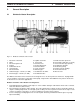
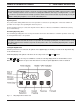
WEBASTO SCHOLASTIC SERIES 2. General Description 2.1 Scholastic Heater Description 2 GENERAL DESCRIPTION Fig. 2-1: Webasto Scholastic Series Heater 1 2 3 4 5 6 7 8 9 Electronic control unit Motor Electronic ignition coil Coupler Combustion air fan Solenoid valve Electrode holder Outlet water pipe - 25 mm (1 in. OD.) Inlet water pipe - 25 mm (1 in. OD.
WEBASTO SCHOLASTIC SERIES 3 3. Functional Description 3.1 Operating your Webasto Scholastic Heater FUNCTIONAL DESCRIPTION WARNING Due to the risk of carbon monoxide poisoning and asphyxiation, the heater must never be operated in closed spaces such as garages and workshops without adequate exhaust extraction. WARNING Due to the risk of fire or explosion, the heater must be switched off while refueling and at fueling stations.
3 FUNCTIONAL DESCRIPTION WEBASTO SCHOLASTIC SERIES NOTE: If the heater is switched on while the engine is at operating temperatures above 68 °C (155 °F) only the operation indicator and the coolant circulation pump will be activated. The engine coolant temperature must fall below 68 °C (155 °F) at the heater before the heater will begin heating operation. NOTE: Switching the Webasto heater on during the cool-down or “after-run” period is allowed. The heater will revert to normal operational mode. 3.
WEBASTO SCHOLASTIC SERIES 3 FUNCTIONAL DESCRIPTION NOTE: We recommend that memory locations 1 and 2 be used for presetting starting times within a 24 hour period of setting the timer. Memory location 3 can be reserved for a starting time within the next 7 days of setting the timer. Location 3 is useful for occasional weekend or field trip operations outside of the normal schedule. By repeatedly pressing the button, starting time program 1, 2 or 3 can be viewed and preset.
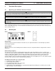
3 FUNCTIONAL DESCRIPTION 3.7 WEBASTO SCHOLASTIC SERIES 7-Day Digital Timer Programming and Operating Instructions Setting the time and day of the week Press the button for more than 2 seconds. Time display flashes. Press the or button to set time of day. Wait 5 seconds. Time is now stored. Day of week flashes. Press or button to set day of week. Wait 5 seconds. Day of week is now stored. Viewing the time With ignition “ON”: Continuous display of current time and day of the week.
WEBASTO SCHOLASTIC SERIES 4. Technical Data 4.1 Scholastic Series Heater Data 4 TECHNICAL DATA The following data is subject to the normal tolerance for heaters, if no tolerance is specified. This is approximately +/-10% in an ambient of 20 °C (68 °F) at nominal voltage. Heater Scholastic Series Design Coolant heater with high-pressure nozzle Heat Output kW (BTU/hr) Fuel 13.1 (45,000) Diesel #1 Diesel #2 and Arctic Fuel Consumption l/hr (gal/hr) 1.5 (0.
4 4.1.1 TECHNICAL DATA Scholastic Series Heater Dimensions Fig.
WEBASTO SCHOLASTIC SERIES 4.2 4 Coolant Circulation Pump Data Flow Rate l/hr (US gal/min) 3406 - 4542 (15 - 20) Rated Voltage (V) 10 - 14 Power Consumption (W) 72 Dimensions mm (inch) Weight 4.2.1 L W H kg (lb.) Hose connection Table 4-2: TECHNICAL DATA mm (inch) OD. 214 (8.42) 106 (4.16) 106 (4.16) 2.5 (5.5) 28.5mm (1-1/8) Coolant Circulation Pump Data Coolant Circulating Pump Dimensions Fig. 4-2: Coolant Circulating Pump Assembly (P.N.
4 4.3 TECHNICAL DATA Tray Mount Dimensions Fig.
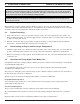
WEBASTO SCHOLASTIC SERIES 5. Installation 5.1 General Information 5 INSTALLATION Webasto will take you step by step through the installation process to ensure successful operation for years to come. The installation must be performed in accordance with the installation instructions provided in this manual. NOTE: This manual does not cover all possible installations. This manual is a general guideline only.
5 5.3 INSTALLATION WEBASTO SCHOLASTIC SERIES Mounting the Heater Tray Kit mounting in existing enclosure on vehicle, i.e. battery box. 1. Ensure that the enclosure is large enough to accommodate the heater. Use the installation template provided with the heater kit. 2. The installation enclosure must provide adequate ventilation for combustion air requirements [20 cm² (4 in²)]. 3. Lay the supplied installation template in the enclosure.
WEBASTO SCHOLASTIC SERIES 5.5 5 INSTALLATION Combustion Air Supply WARNING Due to the risk of carbon monoxide poisoning and asphyxiation, never draw combustion air from inside the vehicles passenger compartment. 1. Never draw combustion air from inside the vehicle, or from areas where fumes or gases can accumulate. 2. The installation housing must provide adequate ventilation for combustion air requirements [20 cm² (4 in²)]. 5.6 Plumbing into the Coolant System Fig.
5 5.6.2 INSTALLATION WEBASTO SCHOLASTIC SERIES Engine and Passenger Compartment Heating WARNING Potential skin and eye burn risk. When working on the coolant system, allow the engine and coolant to cool down and open the radiator cap carefully. Heater Cores arranged in Series A series heating system works in this fashion: Heated water (coolant) from the engine travels through the first heater core in the circuit, then on to the next heater core in the circuit, and on to the next, etc.
WEBASTO SCHOLASTIC SERIES 5 INSTALLATION Fig. 5-6: Series Plumbing Circuit - Transit Model (Engine Rear) 5.6.3 Instructions for Integrating into the Coolant System STOP! CAREFULLY READ AND UNDERSTAND THE FOLLOWING INSTRUCTIONS BEFORE PROCEEDING WITH INSTALLATION! 1. Remove the radiator cap and release system pressure. 2. Close the shut off valves for heating system, if so equipped, or pinch off the supply and return line with hose clamping pliers. 3. Plumb into the system as shown in figure 5.4 or 5.5.
5 8 INSTALLATION WEBASTO SCHOLASTIC SERIES Remove hose clamping pliers and/ or open shut off valves. 9. Purge air from the Webasto heater by opening the bleeder valve screw (see page 2-1, figure 2-1, item 26). 10. Top off engine coolant as per engine manufacturer’s recommendations and re-install the radiator cap. Do not install the previously removed heater hose access covers at this time.
WEBASTO SCHOLASTIC SERIES 5.7 Fuel System 5.7.1 General Description 5 INSTALLATION The fuel is drawn from the vehicles fuel tank through a fuel standpipe. This standpipe can be utilized on vehicles with a threaded port in the fuel tank for this purpose. IMPORTANT! Keep the fuel standpipe 50 mm (2”) from bottom of the fuel tank. 5.7.2 Fuel Supply Fig. 5-7: Fuel Standpipe Installation The fuel standpipe and fuel line must be installed according to these instructions to ensure proper heater operation.
5 INSTALLATION WEBASTO SCHOLASTIC SERIES 2. Install the universal fuel standpipe and 3/8” check valve. Check valve directional indication mark (arrow or symbol) must point in direction of fuel source (fuel tank). - use 1/4” or 1/2” spare port on fuel tank and install fuel standpipe securely in fuel tank, use pipe thread sealant on all pipe threads. 3. Route and secure fuel line from heater to fuel tank. Do not route fuel line over frame rails, always route through or under the frame rail.
WEBASTO SCHOLASTIC SERIES 5.7.3 5 INSTALLATION Fuel Filter CAUTION Check local and State codes and regulations for fuel filter mounting locations. CAUTION To prevent fuel nozzle failure, always use CLEAN fuel from a known CLEAN source for priming fuel systems and filters. Your heater is equipped with a spin-on fuel filter. Fuel filters require changing at least annually and in cases of dirty fuel more often.
5 WEBASTO SCHOLASTIC SERIES INSTALLATION 5.8 Wiring Connections 5.8.1 General Information The control unit is equipped with low voltage protection, therefore it is imperative to keep vehicle batteries in good condition. Red labeling or markings indicating 12 volts identify electrical components for the Scholastic Series heater. Green labeling or markings indicates 24 volt components, which are not suitable for this version of heater.
WEBASTO SCHOLASTIC SERIES 5.8.3 5 INSTALLATION Timer and Switch Connections For switch connection details (pin-outs) see wiring diagrams (fig.5-13, 5-14) on pages 5-13 and 5-14 appropriate to your installation. Fig. 5-10: On/Off Switch Pin-Out 1 2 Terminal 86 of Relay K1 4 Chassis Ground (Negative) 8 To Control Unit Terminal Location B3 10 To Vehicle Ignition Signal (Positive) 11 Terminal 87 of Relay K1 or Constant 12 Chassis Ground (Negative) 3, 5, 6, Fig.
5 5.8.5 INSTALLATION Wiring Diagram – Scholastic Series Heater Fig.
WEBASTO SCHOLASTIC SERIES 5.8.6 5 INSTALLATION Wiring Diagram – Chassis / Power Harness with Switch 0030777A Option 1345-03 Fig.
5 5.8.7 INSTALLATION WEBASTO SCHOLASTIC SERIES Wiring Diagram – Chassis / Power Harness with Switch 0030522A Option 1345-03 Fig.
WEBASTO SCHOLASTIC SERIES 5.8.8 5 INSTALLATION Wiring Diagram – Chassis / Power Harness with Digital Timer Model 1531 0030778 Option 1345-04 Fig.
5 5.8.9 INSTALLATION WEBASTO SCHOLASTIC SERIES Wiring Diagram – Chassis / Power Harness with Digital Timer Model 1531 0030512 Option 1345-04 Fig.
WEBASTO SCHOLASTIC SERIES 5.9 5 INSTALLATION Initial Operation 1. Check your installation for: - loose nuts and bolts. - exhaust pipe routing and clamp tightness. - loose hose clamps. - routing and securing of wiring and heater hoses. - kinked or pinched hoses. - battery connection and polarity. - disconnect control thermostat on Webasto heat exchanger (red and green wire, see page 2-1, figure 2-1, position 13). 2.
5 INSTALLATION WEBASTO SCHOLASTIC SERIES 15. Complete the warranty card and send to Webasto Thermosystems (There is an area on the last page of this manual for recording information that is useful when calling for technical support). NOTE Necessary information to complete the warranty card can be found on the name plate on top of the heater burner head. The completion of the warranty card will ensure full warranty coverage.
WEBASTO SCHOLASTIC SERIES 6. Heater Maintenance 6.1 Annual Maintenance 6 HEATER MAINTENANCE CAUTION Annual maintenance requires basic product knowledge and maintenance procedures and should only be performed by Webasto trained and certified, skilled personnel. Ask your Webasto representative about training clinics. The Webasto heater requires a minimum of maintenance to operate.
WEBASTO SCHOLASTIC SERIES 7. Basic Troubleshooting 7.1 General Information 7 BASIC TROUBLESHOOTING CAUTION Troubleshooting requires profound knowledge about structure and theory of operation of the heater. Troubleshooting may only be performed by Webasto trained and certified, skilled personnel. This section describes troubleshooting procedures for the Scholastic Series coolant heater. Troubleshooting is normally limited to the isolation of defective components.
7 7.3 BASIC TROUBLESHOOTING WEBASTO SCHOLASTIC SERIES Heater Test Unit (Webasto P.N. 440280) The tester unit has been designed to quickly check the proper operation of the various heater components. By using the tester in place of the heater control unit, you are able to manually control the heater to test components and actually operate the unit in heating mode.
WEBASTO SCHOLASTIC SERIES 7.4 7 BASIC TROUBLESHOOTING Test Procedures WARNING Do not attempt to test fire or run heater with burner head open. Ensure burner head is properly closed and secured in place. NOTE Make sure the Water Pump and Motor Switches , are in the off position before connecting to the heater. 1. Setup - Remove connector blocks from heater control unit, inspect for loose wires, corrosion and proper wire connections. - Plug control unit connector blocks into tester.
7 WEBASTO SCHOLASTIC SERIES BASIC TROUBLESHOOTING 3. Manual test running of heater - Turn the WATER PUMP switch “ON” - Turn the MOTOR switch - Push and hold the FUEL SOLENOID VALVE button - Push and hold the IGNITION SPARK COIL button taken place.
WEBASTO SCHOLASTIC SERIES 8 SPARE PARTS LIST Scholastic Series Figure 1 Subject to modification ITEM QUANTITY PART NO. DESCRIPTION REMARKS No Fig. 1 92119B Basic Scholastic Heater 12V Complete – replacement heater only. No Fig. 1 NA Burner Head with Control Unit 12V Completely mounted and connected.
8 WEBASTO SCHOLASTIC SERIES SPARE PARTS LIST Scholastic Series Figure 1 Subject to modification ITEM QUANTITY PART NO. 25 2 432377 Screw M4 x 12 26 2 152269 Serrated Lock Washer M4.
WEBASTO SCHOLASTIC SERIES 8 SPARE PARTS LIST Scholastic Series Figure 2 Subject to modification ITEM QUANTITY PART NO.
8 WEBASTO SCHOLASTIC SERIES SPARE PARTS LIST Scholastic Series Figure 3 Subject to modification ITEM QUANTITY PART NO. 50 1 322083 Solenoid Valve 12V 51 1 386650 Small Parts for Solenoid Valve For item 50 52 1 260487 O-ring 12 x 1.
WEBASTO SCHOLASTIC SERIES ITEM 8 QUANTITY PART NO. DESCRIPTION 75 1 310344 Filter Screen 77 1 260738 Gasket 80 2 488631 Screw with Washer SPARE PARTS LIST REMARKS 82 1 412198 Nozzle Holder 83 1 410799 Pre-heat Element 12V 84 1 19723B Holding Strap 85 1 298816 Bracket 86 1 104012 Pre-heat Thermostat No Fig.
8 WEBASTO SCHOLASTIC SERIES SPARE PARTS LIST Scholastic Series Figure 4 Subject to modification ITEM QUANTITY PART NO.
WEBASTO SCHOLASTIC SERIES 8 Subject to modification ITEM SPARE PARTS LIST Scholastic Series DESCRIPTION Figure 5 QUANTITY PART NO.
8 WEBASTO SCHOLASTIC SERIES SPARE PARTS LIST Scholastic Series Figure 6 Subject to modification ITEM QUANTITY PART NO.
WEBASTO SCHOLASTIC SERIES ITEM QUANTITY PART NO. 8 DESCRIPTION SPARE PARTS LIST REMARKS 182 2 24981A Fuse 15 Amp Use with item 181 182 1 103992 Fuse 20 Amp Use with item 181 183 7 178705 1-Pin Female Connector Housing 184 3 620295 Ring Connector 186 1 82399A Preheat Harness No Fig. 1 900012 Inertia Switch No Fig.
8 WEBASTO SCHOLASTIC SERIES SPARE PARTS LIST Scholastic Series Figure 7 Subject to modification ITEM QUANTITY PART NO.
WEBASTO SCHOLASTIC SERIES 8 SPARE PARTS LIST Scholastic Series Figure 8 1 1 Subject to modification ITEM 1 QUANTITY PART NO. DESCRIPTION REMARKS 2 901265 Elbow – Brass 90° with Mounting Flange Through floor connection No Fig. 1 901045 Formed Hose Coolant pump to heat exchanger inlet No Fig. 2 901213 Formed Hose Gates 21488 No Fig.
8 WEBASTO SCHOLASTIC SERIES SPARE PARTS LIST Scholastic Series Figure 9 Subject to modification ITEM QUANTITY PART NO. DESCRIPTION REMARKS 224 1 906647 Fuel Standpipe – Complete Includes items 225,226, 227, 232, 233, 234, 235 Includes 1/2 x 1/4 NPT bushing (not shown) 225 1 906118 Fuel Standpipe – Single Line Standpipe only – does not include tank-boss 226 1 900029 Check Valve – One way 227 1 900004 Barb Fitting 228 X 903709 Fuel Line 1/4” ID.
WEBASTO SCHOLASTIC SERIES 8 SPARE PARTS LIST Scholastic Series Figure 10 1 3 2 4 Subject to modification ITEM QUANTITY PART NO. DESCRIPTION REMARKS 1 1 900400 Fuel Filter Head Used with part 900001 2 1 900001 Fuel Filter – FF 104 Used with part 900400 3 2 900401 1/2 x 1/4 Bushing Used with part 900400 4 2 901293 Barb Fitting 1/4” MNPT x 1/8” Hose Used with part 900400 1 905707 Mount Bracket for Fuel Filter Head Used with part 900400 No Fig.
8 WEBASTO SCHOLASTIC SERIES SPARE PARTS LIST Scholastic Series Figure 11 1 Subject to modification ITEM 1 QUANTITY PART NO. DESCRIPTION REMARKS 1 900731 Tray Mount No Fig. 1 901235 Enclosure Cover No Fig. 1 901233 Enclosure Base No Fig. 4 905388 Rubber Grommet 1-3/4” Dia. Groove No Fig. 1 15527A Stainless Steel Exhaust Tube ø38mm x 1m Includes end-cap No Fig. X 353221 Stainless Steel Exhaust Tube ø38 mm Per meter No Fig. 1 367400 Exhaust Clamp ø39... 42 mm No Fig.
WEBASTO SCHOLASTIC SERIES 8 SPARE PARTS LIST Scholastic Series Figure 12 Subject to modification ITEM QUANTITY PART NO. DESCRIPTION REMARKS 1 1 901000 Housing – Impeller MP # 28842 2 1 901013 O-ring MP # 28613 3 1 901015 Impeller MP # 28727 4 1 901017 Seal Assembly MP # 28984 5 1 901019 Adapter MP # 28733 6 4 901021 Screw MP # 28834 7 2 8 1 901023 Motor 12V 2 176591 Connector – Female 6.3 No Fig. Hex Nut – 10-32 No Fig.
8 WEBASTO SCHOLASTIC SERIES SPARE PARTS LIST Scholastic Series Figure 13 Subject to modification ITEM QUANTITY PART NO. DESCRIPTION 255 1 310646 Gauge for Setting Ignition Electrodes 256 1 440280 Diagnostic Testing Unit 258 1 600190 Fuel Pressure Gauge with Adapter No Fig. 1 905491 Extension Harness for Testing Unit No Fig. 1 406244 Combustion Chamber Puller No Fig. 1 No Fig.
The Scholastic Series School Bus Heater Operating Instructions Installation Instructions Service Parts Listing For: Webasto Thermosystems Inc. North America 3333 John Conley Drive Lapeer, MI 48446 Phone (810) 245-2400 Toll-free (800) HEATER-1 Fax (810) 664-7720 Technical Assistance Hotline USA: (800) 555-4518 Canada: (800) 667-8900 Org. 2/2001 50000058A www.webasto.