
Operating instructions


4.8 Wiring Connections
4.8.1 General Information
The control unit is equipped with low voltage protection, therefore it is imperative to keep the
vehicle's battery connections and battery in good condition.
4.8.2 Power Connection to Battery
Power harness connection instructions:
1. Route and secure wire harness from Webasto heater to battery box and cut harness to length.
2. Strip wires and crimp supplied ring tongue terminals to the positive (red) and negative (brown)
wire leads.
3. Clean any corrosion from battery terminals.
4. Connect the leads to the battery terminals.
5. Protect connections with an anticorrosion compound designed for use with electrical connections
and battery terminals.
4.8.3 Switch and Timer Connections
Switch Installation:
1. Select a suitable location in the vehicle dash for the On/Off toggle switch.
2. Drill a 1/2f hole through the dash for the toggle switch.
3. Route harness between heater and dash, secure harness along its length with wire ties.
If possible, use existing hole in fire wall or drill in suitable location. Protect the harness with a
grommet at the fire wall.
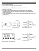
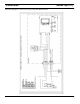
6. Connect the terminals of the harness to the switch. See figure 408 on next page and wiring
diagram figure 410 for reference.
419
Thermo Top C (TTC) 4 Installation
NOTE:
The Webasto heating system will not perform to your satisfaction with a weak battery.
CAUTION!
If welding is to be performed on the vehicle, the main battery cables must be disconnected from the
battery to protect the electronic control unit.
CAUTION!
When drilling holes on the vehicle, do not drill into existing wiring or other mechanical components.