Coolant Heater Thermo Top (TTC) Operating Instructions Installation Instructions
Thermo Top C Installation / Operation Manual Contents Contents 1. Introduction 1.1 General Description ........................................................................................................ 101 1.2 Legal Provisions ............................................................................................................. 102 1.3 Meaning of Warning, Caution and Note.......................................................................... 102 2.
Contents Thermo Top C Installation / Operation Manual Contents 6. Basic Troubleshooting 6.1 General Information ........................................................................................................ 6.2 General Failure Symptoms ............................................................................................. 6.3 Heater Lockout Reset Procedure ................................................................................... 6.4 PC Diagnostics Kit ............................
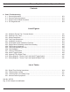
Thermo Top C (TTC) 1. Introduction 1.1 General Description 1 Introduction Fig. 101: Webasto Thermo Top C Coolant Heater 1. 2. 3. 4. 5. Control Unit. Combustion Air Fan Assembly Combustion Air Inlet Connection Pipe Coolant Circulating Pump Coolant Inlet Connection Pipe 6. 7. 8. 9. 10. Coolant Outlet Connection Pipe Fuel Inlet Connection Pipe Exhaust Outlet Pipe Combustion Chamber Heat Exchanger The Webasto TTC is designed for Class 3-7 vehicles.
1 Introduction 1.2 Thermo Top C (TTC) Legal provisions Heater installation must be performed in accordance with the manufacturer`s installation instructions. Any deviation from these instructions are only permitted with the written approval from Webasto Thermosystems Inc. It is the dealer's responsibility to approve installations not performed by Webasto trained personnel. Installation not complying with the installation instructions release Webasto Thermosystems Inc. from any product liability.
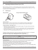
Thermo Top C (TTC) 2. 2 Operating the Webasto Operating the Webasto Thermo Top C (TTC) Before switching on theTTC, set vehicle heating system to the heat position and open any shut off valves. Depending on the type of control installed in the dashboard of the vehicle, the TTC can be operated by the following methods. 2.1 Switching On Using a Switch: Using the Optional Digital Timer: Using the Switch: When the switch is used for turning ON the TTC, the operation indicator (toggle) lights up.
2 Operating the Heater Thermo Top C (TTC) WARNING! Due to the danger of poisoning and asphyxiation the heater must not be operated in enclosed spaces such as garages or workshops without adequate exhaust extraction or ventilation. The Thermo Top C (TTC) will cycle on and off until: 1. The toggle switch is switched OFF 2. The fiinstan heatf button is pressed once again, signaling heater to shut off. 3. Time has elapsed on the timer. 4. The vehicle battery voltage drops below 9.
Thermo Top C (TTC) 2 Operating the Heater Preselected Starting Times The preselected starting time is the time at which the timer switches the heater on automatically. We recommend that memory locations 1 and 2 be used for presetting starting times within 24 hours of setting the timer. Memory location 3 can be used for a starting time within the next 7 days of setting the timer. Operating Time The period of time during which the heater is in operation is referred to as operating time.
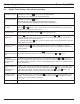
2 2.4 Operating the Heater Thermo Top C (TTC) Digital Timer Setting / Operating Instructions Switching the heater on Manually: by pressing the button (continuous heating mode) Automatically: by programming the heater starting time Switching the heater off Manually: by pressing the button Automatically: after the programmed operating time has elapsed. With the heater running: by programming the remaining operating time.
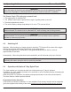
Thermo Top C (TTC) 3. Technical Data 3.1 Technical Data 3 Technical Data The following data is subject to the normal tolerance for heaters, if no tolerance is specified. This is approximately +/-10% in an ambient of 20 °C at nominal voltage. Heater Thermo Top C (TTC) Diesel Design Heat Rating: Input Output Fuel Fuel Consumption: Coolant heater with evaporator burner (Ferro-Tech Technology) - full load - partial load - full load - partial load 6.14 kW (20,960 Btu/hr) 3.1 kW (10,480 Btu/hr) 5.
3 3.2 Technical Data Heater Dimensions Fig. 301: Heater Dimensions Fig.
Thermo Top C (TTC) 4. Installation 4.1 General Information 4 Installation Webasto will take you step by step through the installation process to ensure successful operation for years to come. The installation must be performed in accordance with the installation instructions provided in this manual. WARNING! Asphyxiation risk! The heater must not be installed in either the driver's compartment or in the passenger area of the vehicle. NOTE: This manual does not cover all possible installations.
4 4.3 Installation Thermo Top C (TTC) Mounting the Heater Fig. 402: Permissible Heater Installation Positions WARNING! Asphyxiation risk! DO NOT mount heater inside passenger, sleeper or storage areas. CAUTION! The openings of the water connecting pipes must never point in a downward direction in any installation position. Damage to heater will result due to trapped air in heat exchanger. CAUTION! The heater must not be installed in the immediate vicinity of or above hot vehicle parts.
Thermo Top C (TTC) 4.4 4 Installation Exhaust Pipe Connection WARNING! Asphyxiation risk! Exhaust pipes must be so routed that the possibility of exhaust fumes entering the vehicle is unlikely. CAUTION! Route the exhaust pipe in such a way as to prevent touching or being directed toward any part of the vehicle that may be damaged by heat (i.e., brake lines, electrical wiring, hoses). NOTE: Additional flexible exhaust tubing is available from your Webasto Distributor or Dealer under part number 900126.
4 Installation 4.6 Plumbing the System 4.6.1 General Information Thermo Top C (TTC) The TTC with coolant circulating pump must be mounted at least 6" (15 cm) below the lowest permissible coolant level of the vehicles cooling system. Minimum amount of coolant in the cooling system should be at least 1.0 US gal. (4.0 l). Independent heating systems require a minimum of 3.0 US gal. (12.0 l). A minimum of 10% of a good quality antifreeze should be maintained in the cooling system at all times.
Thermo Top C (TTC) 4.6.2 4 Installation Plumbing the TTC into The Coolant System Fig. 403: Engine Block Preheating Engine Block Preheating: 1. Remove radiator pressure cap and release system pressure. 2. Drain coolant from engine. 3. Plumb the Webasto system as shown above. 4. Refill engine coolant as per engine manufacturer's recommendations and reinstall the radiator pressure cap.
4 406 Installation Thermo Top C (TTC)
Thermo Top C (TTC 4 ,QVWDOODWLRQ 4.6.3 Contents - Engine Connections Caterpillar 3116 ............................................................................................................................. 3176 ............................................................................................................................. 3306 ......................................................................................
4 ,QVWDOODWLRQ Thermo Top C(TTC) Caterpillar Caterpillar 3116 Caterpillar 3176 408
Thermo Top C (T7& ,QVWDOODWLRQ Caterpillar Caterpillar 3306 Caterpillar 3408 409
4 ,QVWDOODWLRQ Thermo Top C (TTC) Caterpillar Caterpillar C-10, C-12 410
Thermo Top C (TTC) 4 ,QVWDOODWLRQ Cummins Cummins B Series 411
4 ,QVWDOODWLRQ Thermo Top C (TTC) Cummins Cummins C Series 412
Thermo Top C (TTC) 4 ,QVWDOODWLRQ Detroit Diesel Detroit Diesel Series 50 Detroit Diesel Series 55 413
4 ,QVWDOODWLRQ Thermo Top C (TTC) Mack Mack E6 / E7 414
Thermo Top C (TTC) 4. Installation 4.7 Fuel System 4.7.1 General Description 4 Installation The pump, fuel line and fuel standpipe are integral to the systems reliability and must be installed according to these instructions to ensure proper heater operation. 4.7.2 Fuel System Limitations CAUTION! If the fuel tank is higher than the fuel pump, the top of the tank may not be more than 20" above the pump. Fig.
4 Installation 4.7.3 Thermo Top C (TTC) Fuel Pump The fuel pump MUST be mounted in a horizontal position in order to function correctly and deliver the proper quantity of fuel. Mount the fuel pump as close to the fuel source as practicable. Do not mount fuel pump near heat sources (exhaust pipes, hot coolant lines, etc.) Pay particular attention to the fuel line and pump limitations as covered in sections 4.7.2. and 4.7.3. Fig. 405: Fuel Pump Mounting (DP 30) 4.7.
Thermo Top C (TTC) 4 Installation Fuel Standpipe Fig.
4 4.7.5 Installation Thermo Top C (TTC) Fuel Line Fuel line, couplers and clamps are provided in the installation kit and are required for proper operation. CAUTION! Fuel line must be secured every 12f (30 cm) and kept away from hot exhaust and moving parts (drive shaft, wheels, etc. NOTE: Use supplied hose clamps to secure all fuel line connections. The TTC has been equipped with fuel line meeting the required specifications for proper operation. The inside diameter of this fuel line is 0.08f (2.
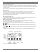
Thermo Top C (TTC) 4.8 Wiring Connections 4.8.1 General Information 4 Installation The control unit is equipped with low voltage protection, therefore it is imperative to keep the vehicle's battery connections and battery in good condition. NOTE: The Webasto heating system will not perform to your satisfaction with a weak battery. 4.8.2 Power Connection to Battery Power harness connection instructions: 1. Route and secure wire harness from Webasto heater to battery box and cut harness to length. 2.
4 Installation Thermo Top C (TTC) Timer installation instructions: 1. Select a suitable location in the vehicle dash for the timer. 2. Temporarily affix timer drilling template to dash or see timer dimensions. 3. Cutout hole to dimensions on template or timer dimensions. 4. Mount timer bezel to dash. 5. Route harness between heater and dash, secure harness along its length with wire ties. If possible, use existing hole in fire wall or drill in suitable location.
4 Installation 4.8.
4 Installation 4.8.
Thermo Top C (TTC) 4. Installation 4.9 Initial Operation 4 Installation 1. Check your installation for: - loose nuts and bolts. - exhaust system routing and clamp tightness. - loose hose clamps. - routing and securing of wiring and heater hoses. - kinked or pinched hoses. - routing and securing of fuel lines. - battery connection and polarity. 2. Top off or refill cooling system with coolant as per engine manufacturers recommendations. 3. Open shutoff valves. 4. Set heater valve to max.
4 Installation Thermo Top C (TTC) 10. Switch OFF TTC heater. 11. Re-tighten hose clamps to 45 in/LB. (5 Nm) and inspect installation for leaks. 12. Complete the warranty card and send to Webasto Thermosystems. NOTE: Necessary information to complete warranty card and ensure full warranty coverage can be found on the heater name plate.
Thermo Top C (TTC) 5. Maintenance of the Heater 5.1 Annual Maintenance 5 Maintenance of the Heater TheTTC heater requires a minimum of maintenance to keep in good operating condition. The following maintenance procedures should be performed annually before each heating season: NOTE For major repair and spare parts, return to your authorized Webasto Thermosystems Specialist. Enclosure Box and Heater - Clean the heater and enclosure box from any accumulated debris or dust with compressed air.
5 502 Maintenance of the Heater Thermo Top C (TTC)
Thermo Top C (TTC) 6. Basic Troubleshooting 6.1 General Information 6 Basic Troubleshooting This section describes troubleshooting procedures for the TTC coolant heater. Troubleshooting is normally limited to the isolation of defective components. CAUTION Troubleshooting requires profound knowledge about structure and theory of operation of the heater components and may only be performed by skilled personnel.
6 6.3 Basic Troubleshooting Thermo Top C (TTC) Heater Lockout Reset Procedure The TTC is designed with a lockout safety feature built in to the control unit. After 3 consecutive unsuccessful startup attempts, the heater will lock itself out from any further start attempts. The heater may also enter the lockout mode after experiencing an overheat condition. The following procedure will clear the lockout mode and reset the heater for normal operation: 1.
Org. 3/2000 Rev. 3/2013 907512A Webasto Thermo & Comfort N.A., Inc. 15083 North Road Fenton, MI 48430 Technical Assistance Hotline USA: (800) 860-7866 Canada: (800) 667-8900 www.webasto.us www.techwebasto.