
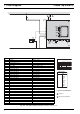
Technical data

Thermo Top E and Z/C 9Repair
3
9.2.2 Combustion Air Fan, Replacement
CAUTION
In case of Thermo Top E and C the circulation pump must
be removed first (see 9.2.1.1).
9.2.2.1 Removal
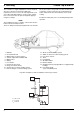
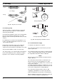
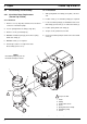
1. Carefully lever off cover (6, Fig. 902).
2. Disconnect electrical connector of combustion air fan.
3. Remove screws (11).
4. Withdraw combustion air fan (1) from burner housing
(5) and fuel pipe (9).
5. Remove gasket (2) and discard.
6. Perform procedures on components after
disassembly (refer to 9.1.1).
9.2.2.2 Installation
CAUTION
For the sealing between combustion air fain and burner
housing two gaskets (2, Fig. 902) are available or
contained in the spares kit. One paper gasket and one
rubber gasket with beads on one side to be used as
follows:
NOTE
A new combustion air fan has a groove for the gasket in
the mounting flange fan to burner housing.
Combustion air fan new –
Control unit / heat exchanger with burner housing
new = rubber gasket
Combustion air fan old –
Control unit / heat exchanger with burner housing
old = paper gasket
Combustion air fan old –
Control unit / heat exchanger with burner housing
new = paper gasket
Combustion air fan new –
Control unit / heat exchanger with burner housing
old = rubber gasket
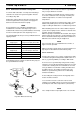
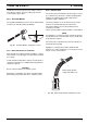
1. Position new gasket (2) on burner housing (3).
2. Slide combustion air fan (1) onto fuel pipe (9) to bring
fan into installation position.
3. Secure combustion air fan (1) with screws (11).
Torque tighten screws to 4 ± 0.4 Nm.
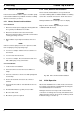
4. Plug on electrical connections of combustion air fan.
5. Install circulation pump as required (see 9.2.1.2).
6. Plug on cover (6) and engage.
7. Perform CO
2
setting (see 6.2.6).