
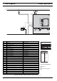
Technical data

8 Servicing Thermo Top E and Z/C
2
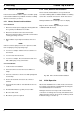
The coolant hoses supplied by Webasto must be installed,
other hoses must meet at least the DIN 73411
requirement. The hoses are to be routed upwards as far
as possible and without kinks to ensure proper venting.
Hose connections must be protected against slippage
using hose clamps.
NOTE
The installation of the hose clamps of the heater must be
between the bead and the heater.
The hose clamps must be torque tightened to 2.0 + 0.5 Nm.
Prior to the heater's first operation or after renewal of the
coolant the cooling system must be carefully bled. The
heater and the lines must be installed to ensure static
venting.
Insufficient venting may cause overheating during heater
operation.
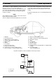
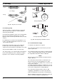
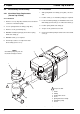
Fig. 802 Example for Heater Installation in Passenger Vehicle
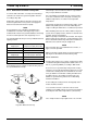
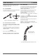
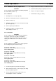
Fig. 803 Fuel Supply
1 Radiator
2 Coolant thermostat
3 Water pump (of vehicle engine)
4 Vehicle engine with standard outfit
5 Water heater
6 Battery
7 Fuse holder
8 Control unit (in heater)
9 Relay (for vehicle air fan)
10 Control valve of vehicle heating system
11 Heat exchanger of vehicle heating system
12 Air fan of vehicle heating system
13 Switch for air fan of vehicle heating system
14 Fuse box in vehicle
15 Timer
16 Fuel tapping
17 Air intake muffler
18 Exhaust muffler
19 Circulation pump (only applicable for supplementar
y
heating)*
20 Fuel dosing pump
* part of modification kit
max. 3 m
i ø 2 mm
i ø 2 mm
S
H
i ø 2 mm
l
1
l
1
i ø 2 mm
l
2
l
2
HG
HG
l
1
+ I
2
≤ 7 m
l
1
≤ 1.2 m
l
2
≤ 5.8 m