
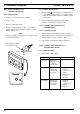
Technical data
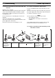

7 Circuit Diagrams Thermo Top E and Z/C
2
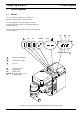
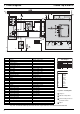
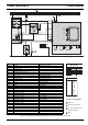
Fig. 702 Automatic Switching Circuit for Thermo Top E and Z/C, 12 V Timer and Telestart T60
ϑ
ϑ
4
Item Nomenclature Remark
A1 Heater Thermo Top E or Z/C
A2 Control unit
A3 Connector box
A4 Telestart receiver T60
B2 Temperature sensor
E Glow plug / flame sensor
F1 Fuse 15 A Flat fuse SAE J 1284
F2 Fuse 1 A Flat fuse SAE J 1284
F3 Fuse 25 A Flat fuse SAE J 1284
H1 LED (in item P) operating indicator light
K3 Relay (in item A3) vehicle air fan
M1 Motor combustion air fan
M2 Motor circulation pump
M3 Motor vehicle air fan
P Timer, digital for timer operation
S1 Switch for vehicle air fan depending on vehicle S1 or S2
S2 Switch for vehicle air fan depending on vehicle S1 or S2
S5 Switch summer/winter switch
X1 Connection, 6-pole
X2 Connection, 2-pole water repellant
X3 Connection, 2-pole water repellant
X4 Connection, 2-pole water repellant
X5 Connection, 2-pole water repellant
X6 Connection, 2-pole water repellant
X8 Connection, 2-pole HF, coaxial
X9 Connection, 4-pole
Y1 Dosing pump
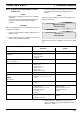
Wire Gauges
< 7.5 m 7.5 - 15 m
0,5 mm
2
0,75 mm
2
1,5 mm
2
2,5 mm
2
4,0 mm
2
0,75 mm
2
1,5 mm
2
2,5 mm
2
4,0 mm
2
6,0 mm
2
bl
br
ge
gn
gr
or
rt
sw
vi
ws
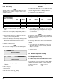
Wire Colours
blue
brown
yellow
green
grey
orange
red
black
violet
white
Legend for circuit diagrams
1 Diagnosis
2 Outside air temperature
3 Vehicle heating air fan fuse
provided in vehicle
4Option